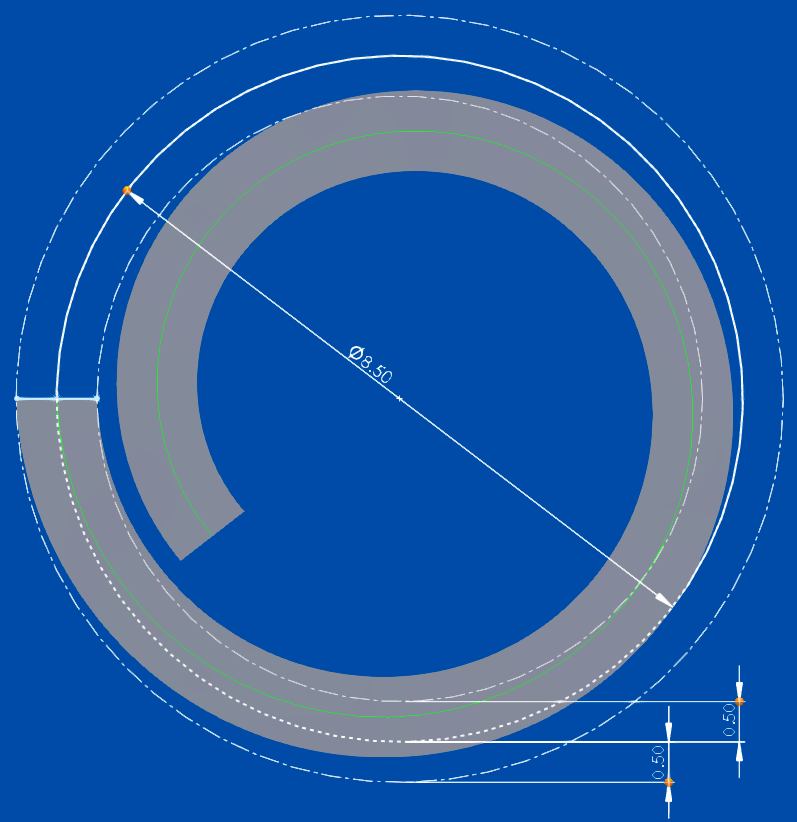
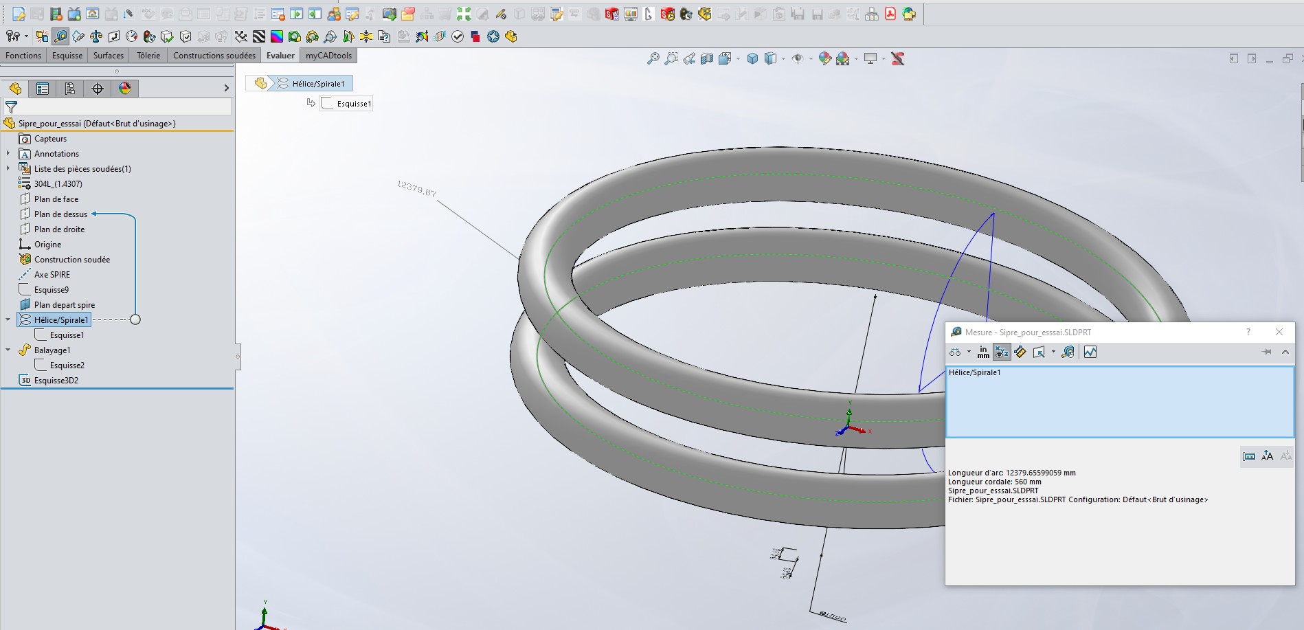
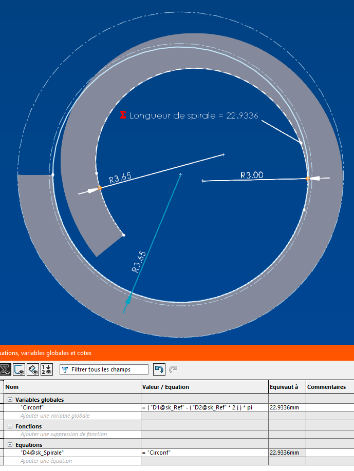
Hello, I would like to measure and/or rate the length of this spiral (in green on the image) to make sure that its length corresponds to the central perimeter of the circle of ⌀8.5mm when " unfolded ". More precisely, the goal is that by inserting a cylinder of ⌀7.5mm into this flexible spiral it encloses it by forming a closed circle of ⌀7.5mm inside.
Hello; Is it a flat coil or does it have a " step "?
If they are flat: I would create a new sketch on the " top " plane (as on the screenshot) and then using the sketch options (whose name I have forgotten for now), in short, I will convert the coil into a sketch, and there, it should be possible to measure the diameters and distances (either with the measure tool, the dimension tool with luck and, Let's be crazy, with the " trajectory " rating option.
if the coil has a " step ", the principle remains the same but with a 3D sketch, in this case it will only be possible to convert the extrusion profile (the axis)...
The pitch is also arbitrary, it is to move it away from the inner wall and will depend on the 3D printing tolerance. I would like to keep a fixed length, equal to the perimeter (about 26.70mm), regardless of the pitch chosen.
" Listen, let the police do their job, but as soon as we have more information, know that you will be the first to know " … I don't have access to my PC (temporarily)...
They whisper in my ear that I should use " Silhouette entities"...
I go like that with SW2022SP4. 1=> You select the neutral fiber of your spiral with the dimensioning tool, it should do it. 2=> You select the neutral fiber and you convert the sketch and add the dimension. 3=> Otherwise just with the measure tool
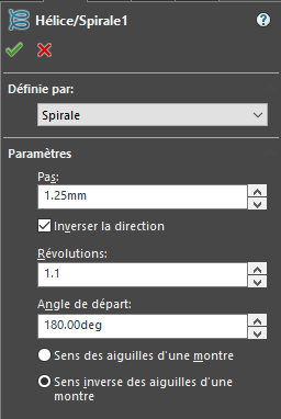
So with the quotation tool, it doesn't work. On the other hand, with the measurement tool (which I forget too often) it works, it gives me the length well, that's already it.
Now if I could link the length of the neutral line of the spiral with that of the circle by an equal relation, that would be perfect.
I must be dick or miro because I can't find " convert the sketch ".
I find " convert entities " but it only works if I select the sketch of the circle that serves as the basis of the spiral, so it creates a 3d sketch of the circle, but no way to do the same thing by selecting the spiral
I have never succeeded in creating a relationship between the measured dimension and the sketch of the neutral fiber of the spiral... We can create sensors with alerts when a given distance is exceeded, but it's not the easiest to manage.
I can't come up with the equation to make the same spiral... Anyway I can't rate the curve either... Another 10 years to do this because of SW's shortcomings
If anyone has a formula for the ratio between step/revolution/length to find the revolution as a function of step and length, I'm all for it.
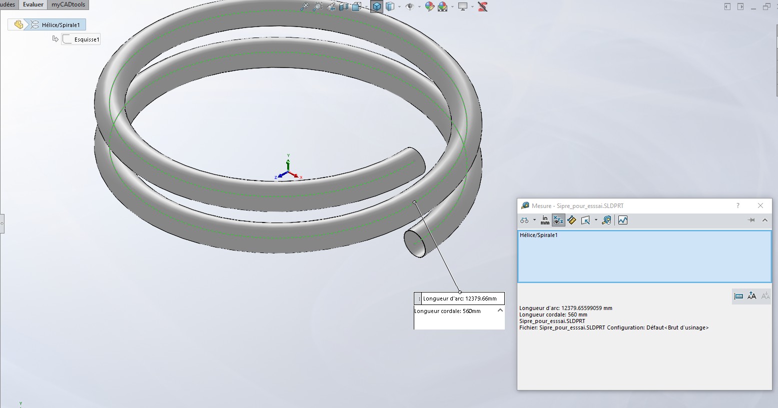
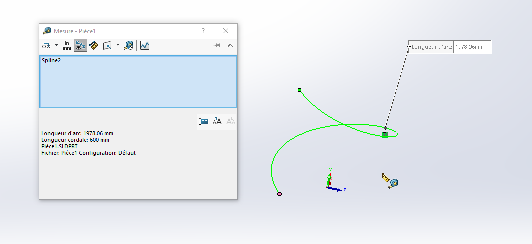
To convert a @Sylk helix or spiral, simply create a 3D sketch, select your spiral and press convert entities. And then you measure the length of your sketch
My shrink asks me never to answer this type of question (probably because of social conventions...)
With a little video perhaps?
But no solution yet for the listing...
Although: By creating a global variable " NbRevolution " whose value is equal to 1.1 By associating the corresponding dimension " revolve value" of the "Helix/spiral " sketch with this global variable. We also need the " Distance " sensor mentioned above:
With all this, it is possible to use " Design Study" from the "Evaluate" tab: In Variable: declare the global variable " NbRevolution ". The objective: The " mesurexx " sensor.
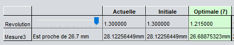
It is now possible to vary the " NbRevolution " value between a mini and a max. And to set the " Measurement " lens to "Near" 26.7mm...
Spoiler alert: it would take 1,215 revolutions for the axle distance to be 26,668 mm.
The macro attachment claims to do the job... Before starting the macro, simply select the spiral in the build tree The radius of the circle is recovered by identifying the sketch of the spiral. The search for the number of revolutions is done by iterations, on a principle no doubt close to that of the design study proposed above by @Maclane . The calculated value is assigned to the spiral.
First of all, thank you to each of you for your ideas that have allowed me to move forward.
Eventually, the scale and moderate flexibility of the material led me to modify the spiral, as the end radius of the loop was too small to unfold properly.
So I mixed arcs and spiral to get a less tight final radius, which allowed me to use trajectory dimensioning on this composite curve, which was not possible on the spiral alone (another absurdity).
From there I was able to directly link a global variable to this dimension, a variable containing the formula for calculating the circumference according to the diameter of the inner circle of the base of the spiral (corresponding to the outer diameter of the host cylinder - the tightening tolerance).
I therefore see myself under a moral obligation to modify the best answer as being that of @Maclane which, by the following sentence, comes closest to the solution adopted: