I have a .sldprt file with multiple sketches, A; B and C I want to put sketches A and B in one layer, sketch C in another layer. Sketches are designed with equations and relationships.
The purpose of this is to export a dxf of the sketches with the layers to reimport it into another software allowing me more advanced processing for manufacturing.
I can't use layers, neither in .sldprt nor in .sldrw
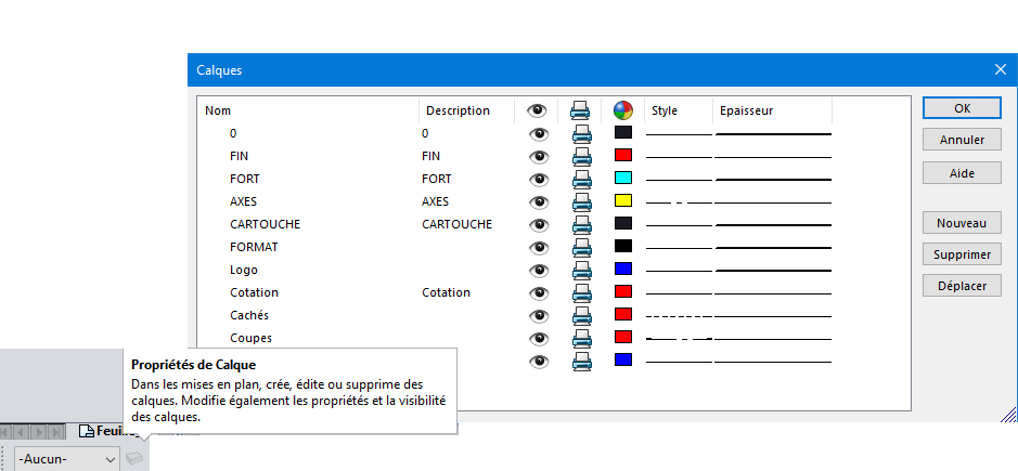
Hello; Layers are not available in sldprt. On drawings (*.slddrw), on the other hand, it is possible to " switch " sketches to pre-defined layers: => " Layers " toolbar + Layer property: Create your different layers with color, style and thickness (Example):
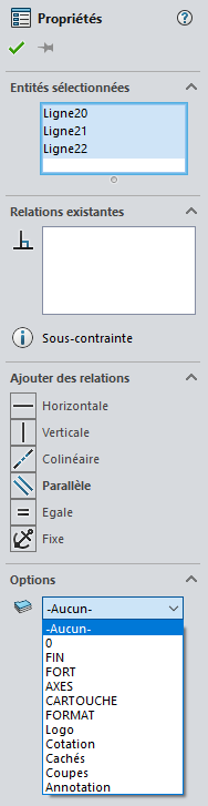
Then select the sketch to send to a specific layer: Expand the " Options " and choose the destination layer for your selection.
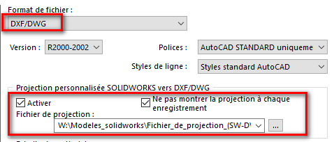
Be careful, you also have to manage the printing of the layers if you export your drawing to formats (DWG or DXF).
to do this, you have to go to the export options (system options/" Export " tab) => DXF/DWG export format: => Activate and create the projection file:
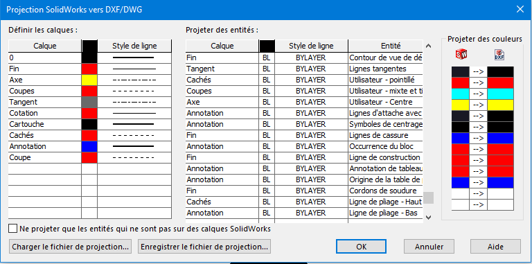
This file allows you to choose how each Solidworks layer will be converted to dxf or dwg (autocad) layers Example of a projection file:
Thank you for your valuable answer. I did create the layers in my drawing file, however I can't choose which layer to apply in the sketch options, because I can't access the sketch properties as on your image
Unfortunately, it is not possible to select a sketch in the feature manager and assign a layer to it. So you have to select each segment in the MEP and then assign it a layer.
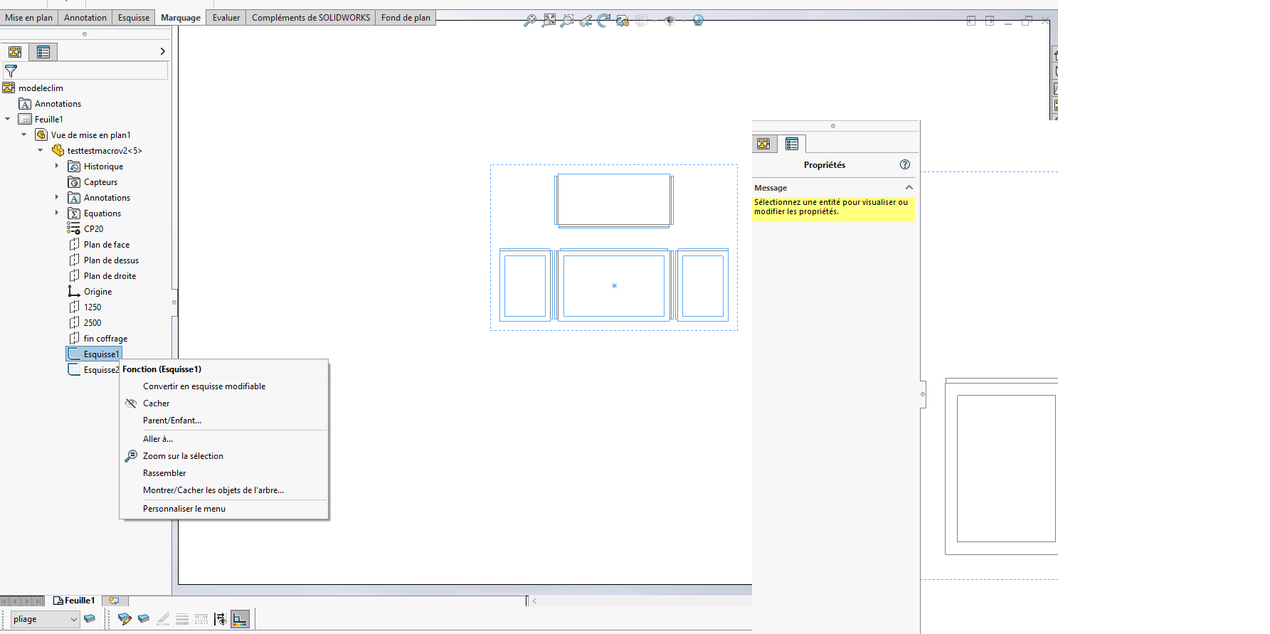
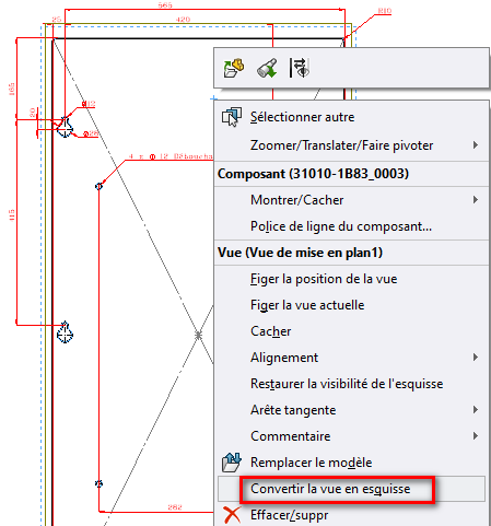
Looking at the screenshot of @nicolas_simon_1 , I think it would be easier to convert the sketches from the creation tree (FeatureManager) to sketches in the drawing: (Convert to editable sketches) Or directly in the view (right cic):
It all depends on the quantity to be processed...
Taking a closer look at the screenshot... ??? Is it already an attempt at macro?
I would only have 3 different sketches in the final file. Unfortunately, I don't have the " convert view to sketch " feature, the only one I have is: " convert to editable sketch"; but this does not produce any change.
Yes I tried a macro because I thought that my need to put a sketch in a layer was easily processed by the AI, obviously this is not the case
How can I get this " convert view to sketch" function?
I have put the original part file for you, this file generates the pattern for 4 pieces constituting a box.
My goal was to modify the equations in order to have the sketch of these 4 parts automatically generated, and to be able to export this new updated sketch in DXF, with the outlines in one layer, the bend lines in another
This while doing as little processing as possible, because it's an operation that I'll probably have to repeat several dozen times a day, I'd like to automate as much as possible to avoid mistakes
My question is: Why sketches? I think that a management of this type of component should rather go through the Families of parts and 3D components... This, along with the management of layers and stroke types presented above, should meet a lot of your requests.
Note: I didn't even try to open your room... since you didn't indicate the version of Solidworks from which it is derived!! Note 2: Sorry this falls on you but it's a rant that has been itching for quite some time.
These sketches serve as outlines for my CAM software which is set up with my cnc machine I then add another sketch layer with the CAM software that handles the homothety, solidworks doesn't. Unfortunately the CAM software does not manage the management of formulas and constraints as well as solidworks, otherwise I would have done everything directly in CAM.
So my goal is as follows, for example: I receive a request for a 1350 x 1200 x 965 case, 63mm slope
→ I enter these values into the equations in my sldprt file → I generate the DXF automatically with the sketches in the right layers → I import the dxf into my CAM software on which I reprocess the well-placed sketches with the right layers + the overlay requiring homothety.
This manipulation must be done several dozen times a day.
(I have solidworks 2022 SP5)
(no worries about the rant, it's just text on a web page)
Manual selection of the 15-20 segments and change layers by hand. If you just increase the size of your sketch, it will follow without any problem and no need to develop a macro for so little.
Exporting sketches to layers now works wonderfully.
However, I just did the test I recorded a drawing with my room and put the sketches in 2 separate layers. (having converted the view to a sketch).
I'm having a problem. Opening the .sldprt file again changes the values of the equations. I save and close When I open the drawing, the dimensions don't update.
Can this be due to the fact that the view has been converted into a sketch?
The ideal is to start from a volume and then in the MEP to change the layers of the edges. Here no volume so no edge so no layer. SW is made for 3d by for a simple sketch representation to be put in plan, hence the PB.
The solution with the volume part works properly I can't make 3 layers, or even two, but having only the outlines of the parts in one layer is a lifesaver.
In addition, everything adapts correctly by rebuilding