Hi all
I am trying to create a part inside an assembly, this part will be used to connect two balls of joints on different orientations.
See the images
piece1.jpg
piece2.jpg
Hi all
I am trying to create a part inside an assembly, this part will be used to connect two balls of joints on different orientations.
See the images
Hello
You go to the Assembly tab and then you click on the arrow on the second icon and you choose new part and then you expand the creation tree and you choose the plane (in a room or whatever) to start designing your part. Or else insert component and new part.
Hello
You go to the Assembly tab and then you click on the arrow on the second icon and you choose new part and then you expand the creation tree and you choose the plane (in a room or whatever) to start designing your part. Or else insert component and new part.
Hello
You go to the Assembly tab and then you click on the arrow on the second icon and you choose new part and then you expand the creation tree and you choose the plane (in a room or whatever) to start designing your part. Or else insert component and new part.
Hello
You go to the Assembly tab and then you click on the arrow on the second icon and you choose new part and then you expand the creation tree and you choose the plane (in a room or whatever) to start designing your part. Or else insert component and new part.
Hello
To extend the proposal of @ac cobra 427, after having created a new piece...
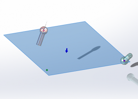
In the assembly, create a plane (PLANE1) using 3 points: the two centers of the spheres, and a third point, distinct from the two previous ones, which can be for example the origin of the assembly.

Then use this plane to constrain the connecting piece, by making its front plane coincide with PLANE1. In this way, the face plane of the connecting piece contains the line joining the centers of the spheres. The face plane of the connecting part is then used as a basis for creating the functions: such as a form of revolution if it is a question of defining a connecting rod...
The advantage of this approach is that if the connecting piece is well designed, it will automatically adapt to a possible movement of the spheres of the neighboring parts.
Kind regards
Hello@tous
@fauteux1959, if I may, and of course if I'm not mistaken, you try to draw a direction bar

If this is indeed the case I don't think that this type of parametric modeling (controlled by an assembly) is adequate, because no matter how much you turn the steering wheel, the wheels will not move the length of this bar and subject to error, in my opinion a simple measurement of the distance between ball joints, independent and smarter modeling,
Kind regards