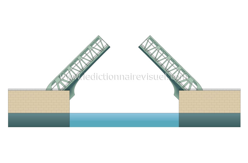
Disagreement between friends, making Levi bridge

Hi all

I am registering on this forum because I have a project to make an electric drawbridge.

During the explanation/diagramming to friends, we came across a disagreement, which I do not understand at all. The subject often comes up in the evening and I feel like I feel a bit lonely (10 of my friends don't agree with me and only 1 is more of my opinion)

To be honest it bothers me a little, if I'm wrong I'd like to know why and understand.

let me explain; I want to put a motor that drives an axis via a reduction gear on the ground. The motor is positioned on one side and drives a fairly robust 5 meter long axis, this axis is held by bearings (3 or 4) and the bearing supports are sealed to the ground.

So I was thinking of putting a motor, to turn this 5-meter axis. My friends think it's better to put 2 of them, one on each side.

From my point of view, it doesn't make a difference to put one on one side, than one on each side 2 times less powerful.

This is where we disagree... And for me their reasoning is not logical. By asking them to detail, for them, it is easier to stop the axis in rotation at 4.5 meters from the motor than at 50 cm, because there is a loss of force coming from the motor.

For me it makes no difference!
 

That there is a loss on the bearings, at the level of the motor or at the level of the reduction gear, ok, it seems logical to me, but that there is a loss at the end of the axle?!  
For me there is not, and if there is I would be very surprised (+ very surprised even, for me it is as logical that when you let go of an object it falls because of gravity...)  ! Even more so if this loss is so important that you have to put 2 engines!

What do you think?


Hello @vogue503

A small diagram would be welcometo see where the axis is.

In addition, we must also mention the weight of the bridge deck (floor).

Have you given up the traditional arrows and chains that lift the Levi bridge.

What about the torque needed at the engine output?

BRIEF! Once you answer these questions, you will immediately see the benefits of one or two engines.

Kind regards

PS: anyway the problem is in my opinion not that of one or two engines but in all the mechanics around it

3 Likes

Already, at the base, I rarely saw 2 (or more) engines mounted in series on anything other than prototypes. This is for a simple reason: managing to synchronize 2 engines is particularly tricky. In this specific case, even when sending the same command to the 2 motors, simply because of the dispersions there is always one motor that will force more than the other, hence a jolt operation.

If we are talking about a bridge of this kind:
or

It is important to know that there is a counterweight at the abutment, which means that the engine produces a low force given the masses involved.

If we stay on a theoretical case of a long shaft resulting in a high torque (strongly offset load), there is a torsional phenomenon (probably the loss of force mentioned by your friends) which may occur depending on the way the load and the motor are connected to the shaft. That's why we put counterweights...

7 Likes

Hello

First of all, I have to ask you to clarify this sentence which is not clear at all, a diagram is worth a thousand words and would be much clearer

"This is where we disagree... And for me their reasoning is not logical. By asking them to detail, for them, it is easier to stop the axis in rotation at 4.5 meters from the motor than at 50 cm, because there is a loss of force coming from the motor. "

From my point of view as a mechanical draftsman, stefbeno is entirely right and that's why you shouldn't put 2 engines but only one.

The synchronization of 2 motors is not simple and more often with Brushless and in your case it will be an Asynchronous motor I guess so you can forget this idea of putting a motor from each end of your shaft

In addition, it avoids having 2 engine mounts, 2 transmissions, 2 couplings.

The real problem with a long shaft is twisting. So depending on the torque that your engine will apply to this shaft it will be necessary

that the material and diameter of the shaft be sized accordingly. Oops of just saw that stefbeno says the same thing in his last message, it's that we agree;) And I also think that's the phenomenon that your friends are talking about.


Good evening

First of all, thank you for your answers and sorry for this late answer, being on the move it's not easy to take the time to answer.

So here is a diagram (made with the means at hand because I'm in a hotel):

1 - solid axle about 2 to 3 cm in diameter

2-motor + transmission (I don't go into the details of the transmission (chain, gear etc...)

3-Drawbridge floor (2mx4m)

4- Sealed IPN

5- Rope

6- Rope reel (Scooter/car wheel?)

7-reinforced concrete

8-Bearing support (X4 on the schematic)

9- Chemical Threaded Rod Fixing in Reinforced Concrete Bearing Bracket

First of all, before going into details, what interests me for the moment is this mysterious loss of power at the end of the axis, so I'll start there.

From what you tell me, you think my friends think that the loss comes from the twisting of the metal. I don't think so because they took these other examples:

-If you put a one-meter rod fixed on a small battery-powered drill, it is not possible to stop the axis in motion near the drill, but after one meter it is possible.

-If at the extreme we put a motor that drives a 100 meter axis on a bearing (as if my drawbridge was bigger but it had nothing to carry) the force at 100 meters from the engine is not the same as at 1 meter from the engine

-"it's like everything, there is a loss of power in the pipes with water or electricity if there is + length" (for me this example has nothing to do with it because here the axis is always the same length...)

Regarding the torsion, I thought I would compensate for the problem by adjusting the diameter/robustness of the axle + putting as much bearing as necessary (by the way there are 3 missing on my diagram, it would be good to have some before and after each rope winder)  can you confirm?

For your other questions (a little off-topic but very interesting!):

For Zozo:

Yes I totally agree, it's the mechanics around it that will take me the most time and I'm very happy to have discovered this forum!

Concerning the weight of the floor, that's the whole problem and that's why I give up the moat! to limit the thickness of the floor to be lifted. If I put a stave, the cost will be + high because for the time being indeed it would require a thick + bcp floor thickness and probably a counterweight system.

For StefBeno and oroux1:

Regarding the disadvantage of mounting 2 motors on an axis, I am well aware of it, it is also the first remark I made when I was told about the 2-motor system.

So we are on a "fortified castle" type bridge.

Can you make an additional side view where we can see the path of the rope?
What is the use of sealed IPN?

In this specific case, the idea of the 2 motors is good but each one must drive its furler independently, so no 5m long shaft and the slight offset between the motors will not be detrimental to the system.

2 Likes

Hello Stefbeno,


Thank you for your answer, indeed the idea of the 2 motors without an axle is not bad:)

It avoids having to mount a 5m axis. On the other hand it poses some additional problems to solve, you would have to weigh the pros and cons between axle and 2 motors.

If one of the motors fails I should not twist the floor, if there is a power cut I must be able to open it manually, and the axis is still practical in this case.

But on the other hand I don't need to bury the system anymore, to dig indeed!

So here is another shema (still as beautiful :P):


We would have to add a system for the start of the opening, I don't really know what to put apart from tilting the IPN to help at the start with gravity, or putting some kind of spring at the top, if you have any ideas I'm interested :)

Regarding the loss of power on the long axis, could you answer if there is one or not please (apart from the torsion).

Thank you

Hello

And like that? the old-fashioned way...

ok you will need two more IPNs, but one motor is enough and it's easier to hold open == block the counterweight

With your assembly, you will also need to provide a cable blockage.

Chrtof


b9718317971z.1_20190122124431_000gjbcqunhn.2-0.jpg
1 Like

Hello Chrtof,

I thought about it but it's too high once closed.

For the blocking of the cable indeed it is to be expected, I don't know how yet, same it is to dig...

For the record, when I see the price of a sliding gate of this size, I tell myself that it can be much more fun, and less expensive to make a drawbridge. I have a lot of points to see, I could possibly detail the steps on this forum for those interested.

To give you an idea of the finished work, here are the specifications:

- 4m opening (truck entrance)

-2m high (breeze seen)

- Opening via 5 to 10 remote controls

- Remote opening via telephone (internet)

-Safety first (foresee all cases where the floor may fall and counter them with safety elements)

- plan for mechanical/electrical failures of the motor(s), plan to be able to open it manually

- have 2 different engine shutdown systems when closing is detected (for example 3 switches that stop the motor, 2 in series that control the "Electronic" shutdown and one for a power control in case of electronic bug)

-take advantage of the Levi bridge system to raise a certain amount of water, to make it fall into the small pond of the vegetable garden next to it to oxygenate the water.

-Possibly, see if it is possible to put a small moat or a ditch under the floor of the drawbridge.

The project is planned for 2021 so I will have time to think about all this:)

The most unclear points for the moment are:

- the acceptance of the town hall

-or find the mechanical elements

- the choice of motor(s)

"I've thought about it but it's too high once closed. "      If you have  2m of deck , at most you will be 4m high.     Let's see if you have the space.

The specifications seem a bit "enthusiastic".   Do you want to pass a truck 4m wide  and 2m high?

"-Possibly, see if it is possible to put a small moat or a ditch under the floor of the Levi bridge. "

Take this into account for the  foundation of your pillars...

Good luck to you

Chrtof


pont.png

To answer the initial question: what happens at the end of a Ø10mm long 1000mm shaft put in the chuck of a drill? Personally I don't try to hold it, I hold on to my wrists.
How can this be justified?
In rdm, there are 3 types of deformation: tension/compression, bending and torsion.
If there is a "loss of power", it means that there is a loss of energy and therefore deformation.
If your friends are still in doubt, offer to try it out...


4 Likes

The biggest problem is going to be this: security.
- when lifting, make sure that there is nothing and no one on the deck (especially if accessible from the public road) at ALL times during the movement;
- When descending, make sure that there is nothing and no one under the deck, even if only in the landing area. If there is a moat, it must be deep enough to allow someone to lodge in it (see the elevator pits) otherwise provide a detection...;
- manage the various cases of failure (what happens in the event of a break of the rope or its anchorage => system BLOCKING the movement (following the previous point, a simple speed limit is not enough).

I doubt that the town hall would accept such a project, even if it were proposed with the guarantee of a professional builder. It would have to be inaccessible from the public road, the risks are far too great.

For the mechanical design part, given the specifications:
- the ropes would be replaced by conventional link chains;
- the 2 motors located at the top of the pillars and drive chain wheels;
- at the other end of the chain (in relation to the deck), a reeving system and a counterweight.
Why hauling: to compensate for the difference in travel.
The counterweight makes it possible to have a balanced system that can be manipulated by hand and to limit the power of the engines to the starting effort.
For the start at the opening, simply leave the deck inclined by 5-10°.

If there is a moat, the deck must support the weight of a vehicle (or part of it).
The wheelbase of an average car is around 2000mm, the weight is 1.5t. It is therefore necessary that your deck, on its supports, supports 3t... This calculation is highly secure but...

Once the deck is sized, you will have its mass and will be able to size the rest. Be careful that the lifting force varies with the inclination.

To come back to safety, the main risk being the rupure of the drive, each of the systems must already be able to support the load with a shock coef. It will then be necessary to find the system that works well so that in the event of a rupture on one side, it blocks on the other almost instantaneously (hence the shock mentioned above).

In the event of a moat, it will be necessary to provide guardrails to prevent people from falling. Depending on the installation, these guardrails will have to be retractable with the lift.

2 Likes

Hello @vogue 103

Before going any further, we should make a synthesis because we have to read between the lines to get an idea of the CdC.

I suggest you make a PDF with a version number so that if you want to follow the epic, you can only open the latest version.

I will summarize some points:

Starting with (drawbridge and not Levi) because the word comes from the Latin levis (light) and also with the meaning of literally lifting lift bridge ( levant. Just as the sun rises.)

So before losing its Latin: I note that your project consists of proposing to a Maîrie to use a horizontal door that rises in a similar way to that of a drawbridge instead of a sliding gate.
Therefore, once lowered, there is no need for a moat because the deck of the bridge can rest on the ground: since it is not to make the pedestrian cross a moat but only to walk on a door placed on the ground.

I see some advantage in the absence of a moat, which is that you can absolve yourself of load problems and standards for this type of structure, which is a resistance of 500 Kg per m² corobored to the length. (otherwise splash in the Tarn)

The second advantage that you have very discreetly highlighted is that of weight. A large door (inspired by an isoplane, adapted to the width and length) will do the trick in the conditions of resisting water if the structure is outside.

I think your friends are talking nonsense with this story of loss at the end of a tree. I still hold my ribs with the story of the drill (I don't do MDR because I value life). All heavy goods vehicles but also cars have driveshafts long enough for six-wheel drive trucks.

Once the torsion is  up to 5°, the torque is fully transmitted.
In fact, with a 40 mm tube  and  Ø 33 inter and a length of 3000 mm and a moment of 391 Nm you have a maximum angle of 4.4° and a T stress of 43.43 MPa (in other words, less than the games you will have elsewhere).

In addition, the maximum effort and when the floor is horizontal and the effort decreases the more you raise the floor. In addition, what needs to be lifted is not equal to the total weight of the floor but only half at the beginning.

Then instead of a chain you use a cable. Ok!! except that if you do a winding on a rim you will not have a constant torque for your engine (the  torque increases at the same time as the diameter increases because of the winding on itself). That said, it's not a big deal, since the torque required decreases beyond 45° of lifting).

If the buckling of the drive shaft is correctly calculated and because you have a very low rotation speed and the end of the shaft takes only a quarter of the total floor, you don't need intermediate bearings at all, which are annoying to put on and  especially to align on a wall or something else.

If we summarize

  1. Don't be afraid with the torque of the geared motor not very powerful (if we are in the case of a imitation door placed on a flat ground.
  2. Instead of using a rim you just have to put four flanges on your tube (two on one side and two on the other side).
  3. a single bearing that can be made of plastic on the side opposite the geared motor
  4. an elastic coupling between the geared motor and the lifting shaft as well as a simple crabo to prevent the motor from blocking and heating up if the limit switch (high door) is incorrectly adjusted or is HS).
  5. Provide a double safety device when the door is in the down position to prevent the cable from winding up in the opposite direction and raising the door.

I didn't understand what the IPN is for unless you think of them as the two right and left posts of the door. In this case, square tubes of 100 to 120 mm are more than enough and are also more aesthetically pleasing, ten times lighter and easier to fix in the ground and also less sensitive to torsion than an IPN only designed for certain types of forces.

The last question to ask yourself is if the through shaft can't simply be at the top of the square tubes (if no truck passes between the posts) then the tube at the top is better because it simplifies the returns and reduces the forces and it makes even fewer parts.

I'm good there!!!! Tell him where I am wrong and above all give the latest details on who or what passes between the posts. Depending on these details, I would give you an aesthetic tip.

Kind regards
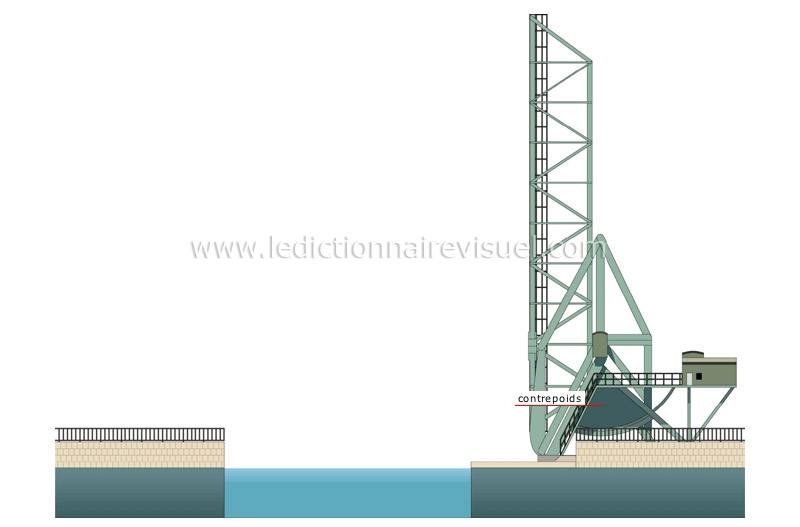
 

Hello

Well at least it's clear, the mysterious loss comes from ineptitude (and maybe from a lack of charisma on my part, it's sad :/) :-P

Oulala Stefbeno! but you are a genius! I had given up on the counterweight because I thought it was going to be too complicated to set it up but I hadn't seen it that way! It's true that if I just put a chuck/weight system, in fact I could carry 100% of the floor, and could therefore use the energy of the motor to go down the floor and not raise it, which I think is + safe, plus if I have animals I can stop it 1m from the ground and continue to make it go down by climbing on it with the car! (of course with a system to check that it is nothing behind)

And it is easy to put for example 2 weights on each side, and that there are the first 2 weights that touch the floor when the floor is at 45°!

In this case, you don't even need an axle or 2 motors I think, the floor should not twist too much if it is pulled only to one side since it is carried by the weights!

For the town hall, so I am in the countryside and on my land and not on the public road, I cannot make it inaccessible, on the other hand I can choose the direction of the opening which can help.

For the axis at the top I didn't want to limit myself in height... I put a 3.5t tractor/food truck/dump truck in it... (that's also why I'm thinking of giving up the fluke, or else I'd need another one to enter what part :P)

Regarding the blocking systems I was thinking of putting systems a bit like seat belts in + sensitive, I would have to find out about it. (if it's possible or not)

For the IPN it is indeed just the posts, I like to oversize, anyway during the design I will plan so that there are only a few elements to change if  I add a moat (weight + floor?) ... Well it will depend on the price...

Zozo if I thought about the rims it was to increase the speed of opening and closing, but it's true that the flanges can be enough depending on the speed at the geared motor output.

On the other hand, what do you mean by level? (item 3)

Your point 4 is great! I was thinking of adding a mechanical locking + power cut part for safety but I hadn't thought about that at all :).

Well anyway, at first, the initial question has been answered, so  I'll pass the post in solved.

I have a lot of projects to finish before attacking this one and I would surely come back to the forum for the drawbridge and other projects for my house (making an elevator for my robot vacuum cleaner, coffee table that goes into a high table with integrated pole dance bar not visible, etc.)

Thank you again for your answers:) It's very constructive and interesting!

I will therefore come back to the subject at the end of next year, and probably before on the forum to present you my other projects ;).


Thank you again:)

2 Likes