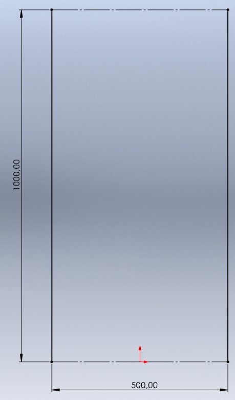
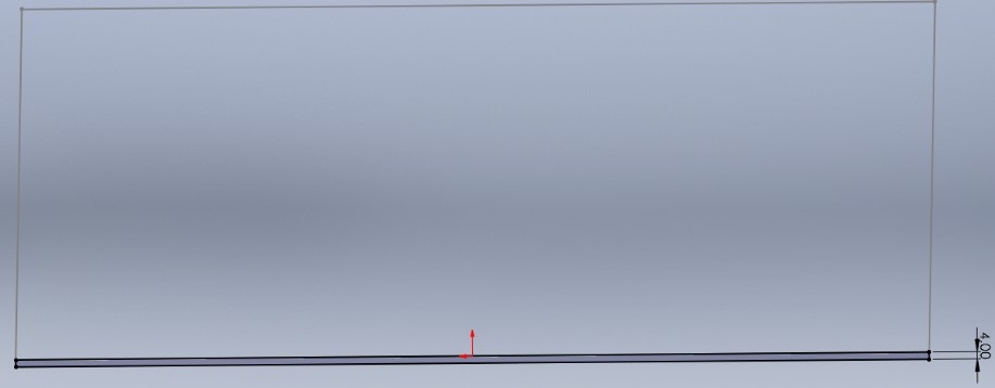
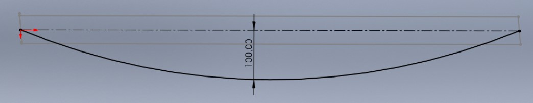
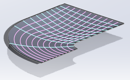
I want to model a flat sheet of 4 mm thickness with a deformation corresponding to a radius of curvature in its center (as if a cylinder were pressing in the middle of the sheet).
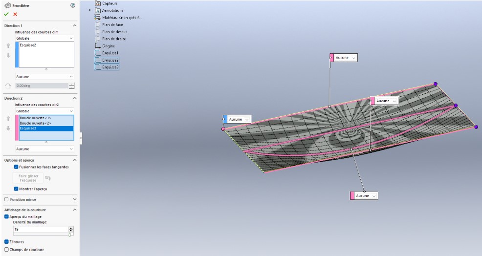
To do this, I use the "Bossing/Boundary Base" function. This method works very well with a rectangular shaped sheet metal.
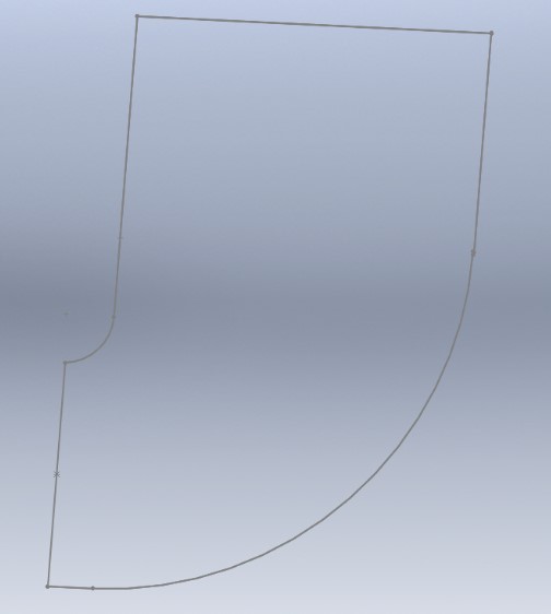
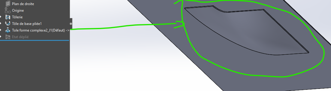
I would now like to apply the same principle to a "J" shaped sheet metal.
@yohann_DEMAILLY I don't know if that's what you expected. Using the @m_blt shape, I created a shape tool and applied it to a sheet metal, resulting in the attached file + the tool
Nb: the @m_blt piece is in an educational version, if you take this piece you have to go through a step to transform it into a usable tool. For your information, this was a problem for me
Thank you so much for the time spent. Indeed, this can be a solution. However, I can't make the shape to make the stamping. Could you detail your method, please?
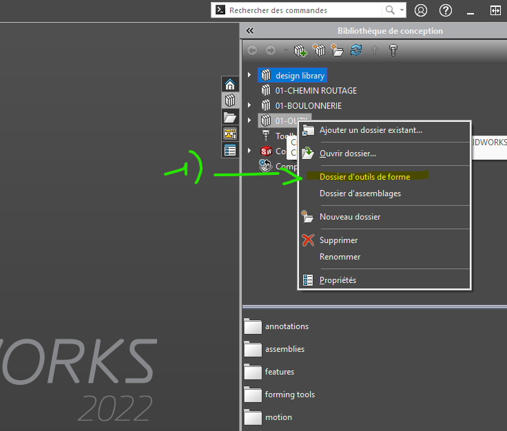
@yohann_DEMAILLY (I have some time to explain) For the stamping tool, you must:
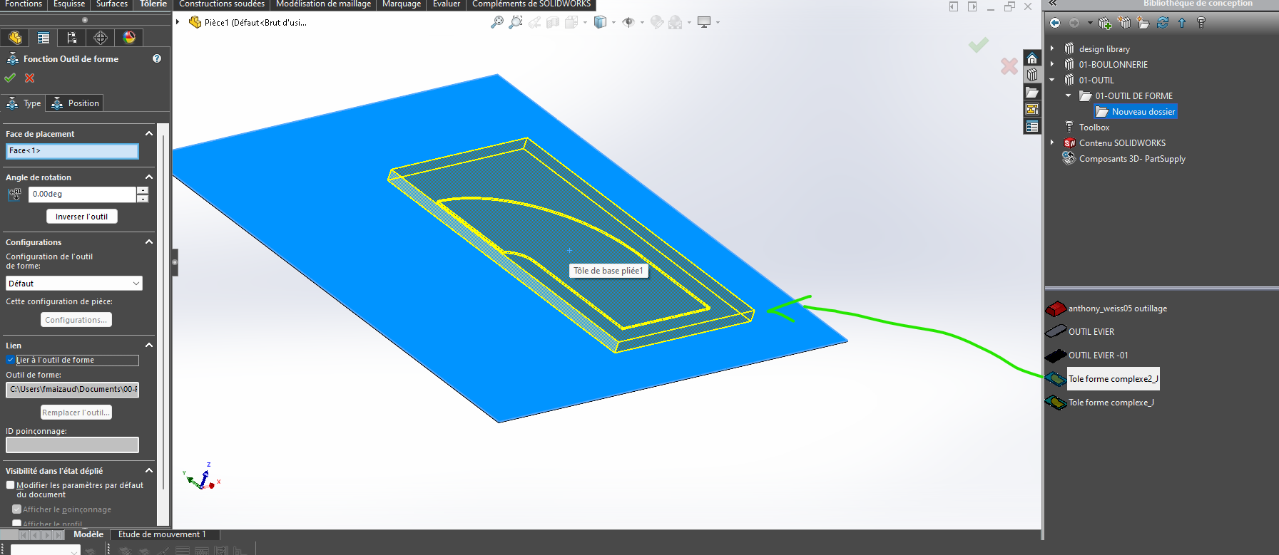
that you tell SW that the folder that contains the tool is a shape tool folder.
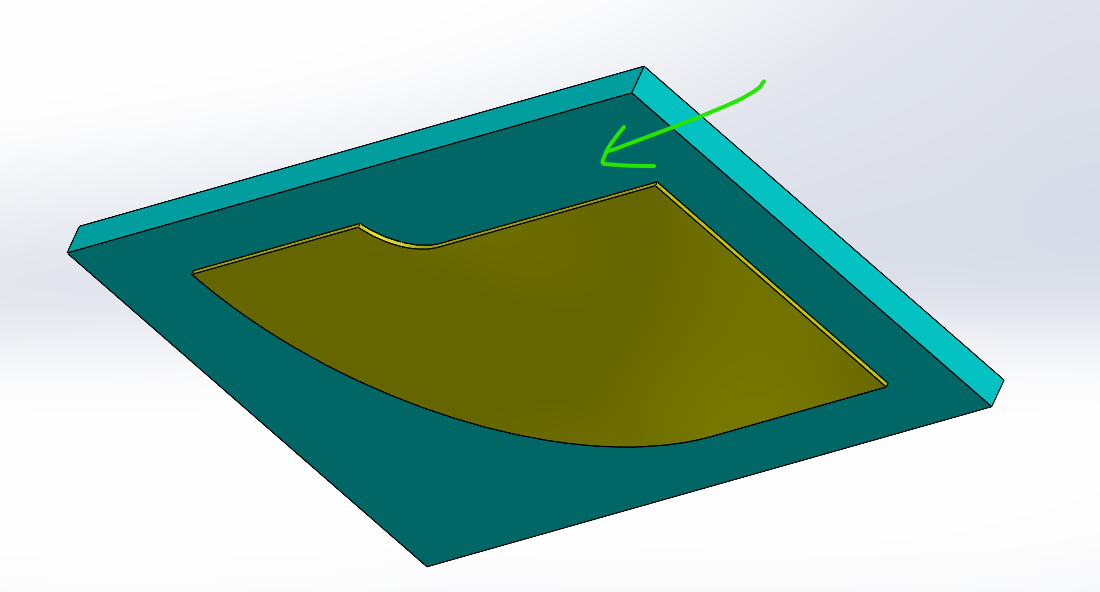
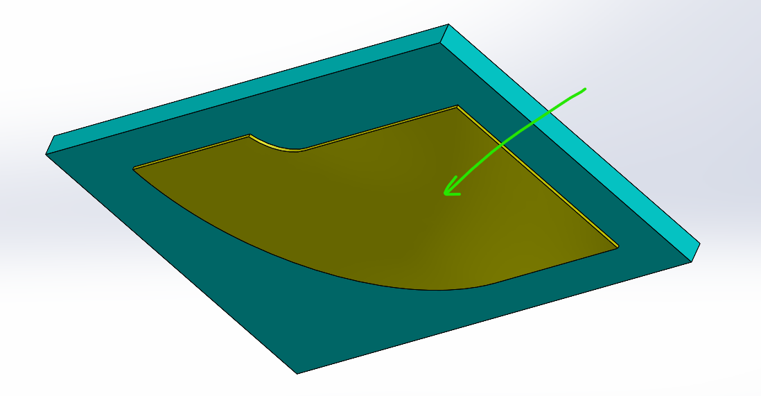
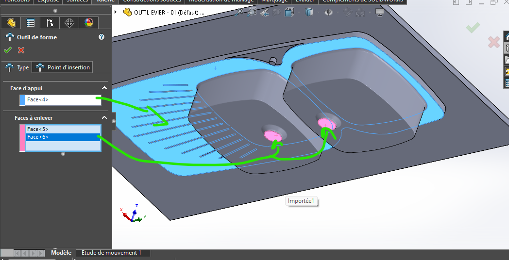
For the forming (or stamping) tool As in the real vi, the tool needs information. You gave me the shape (well @m_blt ), that was the most complicated. Then you have to give it a breakpoint, a surface (in turquoise/green) on the screen print.
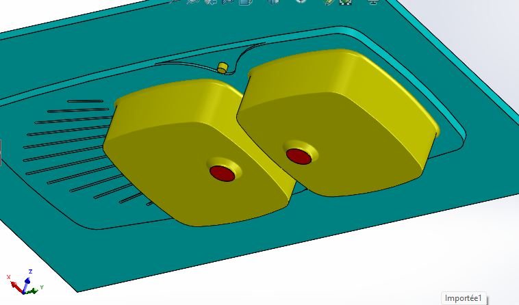
I created a surface on top of the shape and projected the shape back to the shape of the tool, without altering the shape. The shape surface, in yellow. I simply took the form given by @m_blt
(There are also the surfaces to be cut, they are red in color, not present in your case.)
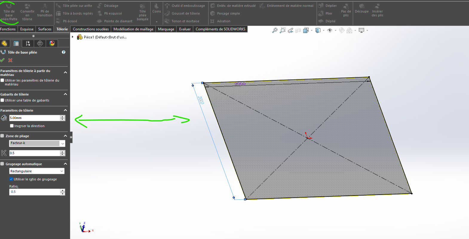
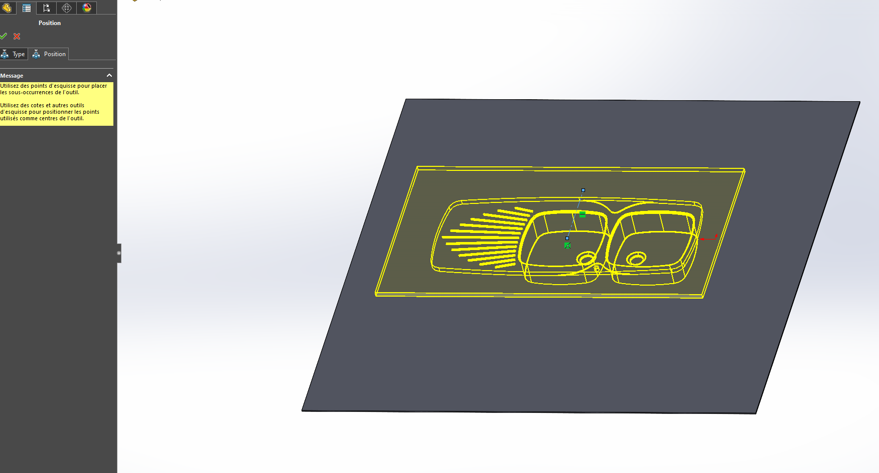
I created in another file a sheet metal with dimensions 2000x2000.
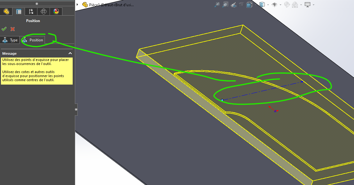
I import the tool (In the tool you can specify the insertion point or indicate it by inserting the shape)
You recover Item1.SLDPRT (251.8 KB) the outline and you remove material around it.