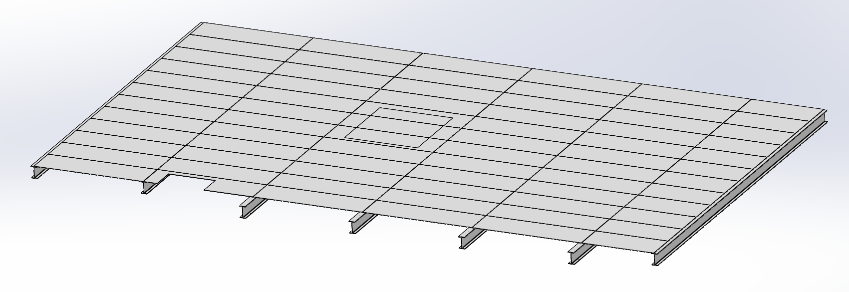
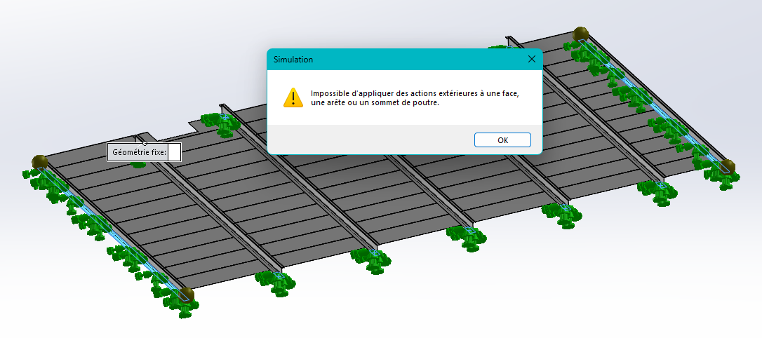
Hello everyone, Here is my mechanically welded platform. I use the simu occasionally; When I launch a static simu I have 4 points on the beams. When I add the imposed displacements I get this: I did several tests before writing here, even on an assembly and it was worse... So I remove the beams. I add my 5000 N charge. During the meshing I have errors. When he finished, the beams in the center disappeared.
The people before me, on this project (dismantling), did not use the welded mechanic (especially because they didn't know it...) to calculate the various structural modifications. In short, should I forget the welded mechanic and hit the beams by hand?
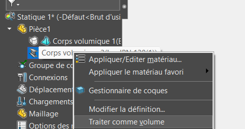
Hello @Cedric_MONKA I had a problem with the Center of Gravity, I had solved the problem by registering a mechanical assembly as a part. Maybe if you turn the whole thing into deadbodies, it can simplify the room for SW.
If you need to redraw everything by projection, retrieve the beam sections in a block. Inserts the block into a room and you extrude. The longest will be the layout.
Thank you, I hadn't thought of turning my assembly into a Part. As for the beam, I didn't take it into account, that's already it. But now, I have an error, in the mesh, on all the plates... I added local interaction, but nothing to do...
Agree with @Scofield1, there is not much interest on a good level PC to use the " beam " model. Unless perhaps the structure is a truss made entirely of beams. The calculation is only a little slower in volume.
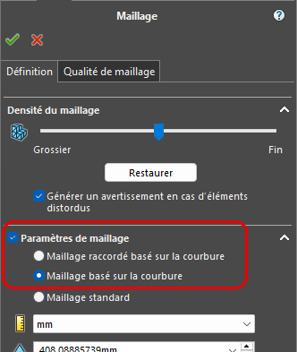
Another point: the standard mesh is often faulted in multi-body or multi-piece assemblies. The " curvature-based mesh" options are generally more efficient.
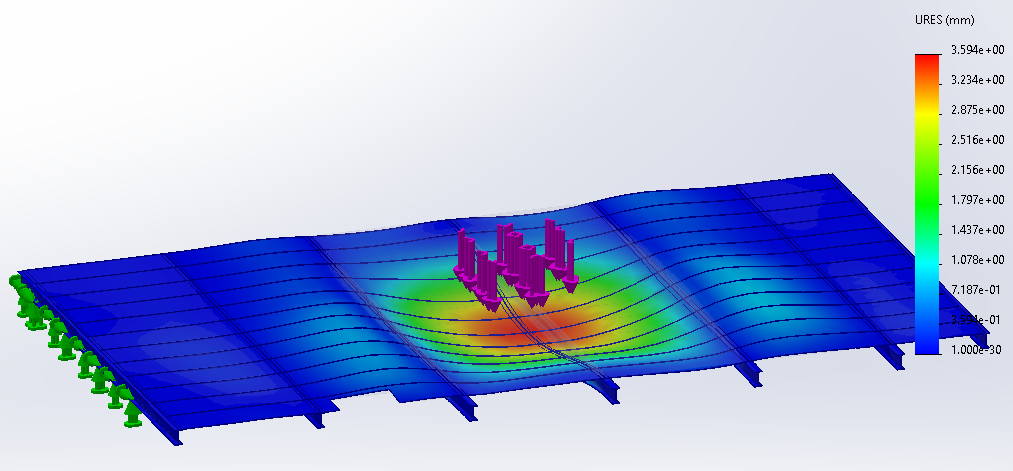
By switching everything to volume, with the option of " curvature-based " meshing, and a load in the central part of the platen, the static simulation runs smoothly (SW 2022) on both models.
I did my calculations on different parts, a meco-welded one where I combined all the bodies, a part with extrusion functions only, and an Asm registered in part. I have different values... So what is the most suitable construction to make a simulation?
Indeed, for simulation, you can't apply actions to edges. To do this, with the " separation line" tool, you can define zones. For example, support area on a beam
For identical computational models modeled differently I had different results, from my point of view it's faster to work on a multi-body file than on an assembly but sometimes you have no choice.
I did my calculations on different parts, a meco-welded one where I combined all the bodies, a part with extrusion functions only, and an Asm registered in part. I have different values...
Obtaining different results is not surprising if the basic models are different: assembly, single-body or multi-body part... If the geometry is similar, the mesh, the materials, the contacts may be different. And even though all of these are visually similar, the simulation uses numerical methods that can be sensitive to small differences.
Finally, it remains to quantify what " different values" mean: on which physical quantities (displacements, stresses, deformations, etc.), at which points in the structure, and with what percentage differences. Evaluating the relevance of the model and the reliability of the result are subtle aspects of FE simulation.
To conclude, I am careful not to give a general answer to the question:
So what is the most suitable construction to make a simulation?
in the simulation module, an ASM or a PRT is exactly the same thing since it works on bodies.
Any body can be considered volumetric, beam or shell. (You can change this hypothesis manually as we have already explained to you here.)
Here you have fairly homogeneous thicknesses, which makes it easier to mesh. But if you had thick bodies and thin sheets, it would become interesting to go through a mixed mesh.
Mixed meshing saves a lot of time on discretization and numerical resolution, but it requires more time for the creation of the model and the contacts between bodies. It's a compromise to be found!
I think it's interesting to create the 2 models, to practice and see if the results converge.