I am affected by anomalies in the reconstruction of 3d models with the management of components according to configurations related to parts or sub-assembly. Using the if statement Function in Solidworks Equations
Dim swApp As SldWorks.SldWorks Dim Part As Object Dim Assembly As Object Dim CompModel As Object
Sub DeleteComponent() Set swApp = Application.SldWorks
' Ouvrir l'assemblage actif
Set Assembly = swApp.ActiveDoc

' Vérifier si la condition est vraie (par exemple, si une dimension dépasse une valeur seuil)
If [Nom de votre dimension] > [Valeur seuil] Then

    ' Parcourir tous les composants de l'assemblage pour trouver celui à supprimer
    For Each CompModel In Assembly.GetComponents(False)
        If CompModel.Name = "Component2" Then

            ' Supprimer le composant s'il correspond au nom donné
            Assembly.RemoveComponent3 False, 0, 0, CompModel

        End If

    Next

End If
End Sub
Before initialization I added the following code: Dim swApp As SldWorks.SldWorks Dim Part As Object Dim Assembly As Object Dim Component1 As Object Dim Component2 As Object
Sub DefineComponents() Set swApp = Application.SldWorks
' Ouvrir l'assemblage actif
Set Assembly = swApp.ActiveDoc

' Définir le premier composant (Component1)
Set Component1 = Assembly.GetComponentByName("NomDuComposant1")

' Définir le deuxième composant (Component2)
Set Component2 = Assembly.GetComponentByName("NomDuComposant2")
End Sub
Now we have to cross-reference the data with the threshold values. My problem is the management by parameterization of a non-buttressed condition on guide columns by integrating the coefficient of adhesion and therefore to determine the maximum lever arm with to cause the phenomenon of blocking; By a static study I have my values, but how to add them at the code level for the macro during initialization and especially what I don't master is to have a dialog box for labels to allow a non-designer to update the model without dedicated training. I don't know if in the forum users an identical approach has been mentioned before, thanks for any clarifications.
Need clarification... What I understood from your message:
You have two drafts of macros that allow you to identify two components of an assembly for one, and to delete an assembly component for the other.
You also have a relationship between geometric parameters that validates or does not validate a non-buttresse condition.
What escapes me is the link between these elements. I guess the goal is to create a macro that tests the property of non-butting between two linked parts, usable by a non-specialist. Question: What should be taken as input to the macro? The two related pieces? The parameters of the non-buttressed condition (dimensions of the guide between the two parts)? The coefficient of friction? What should the output macro do? To return a simple boolean indicating arched or not? Or more...
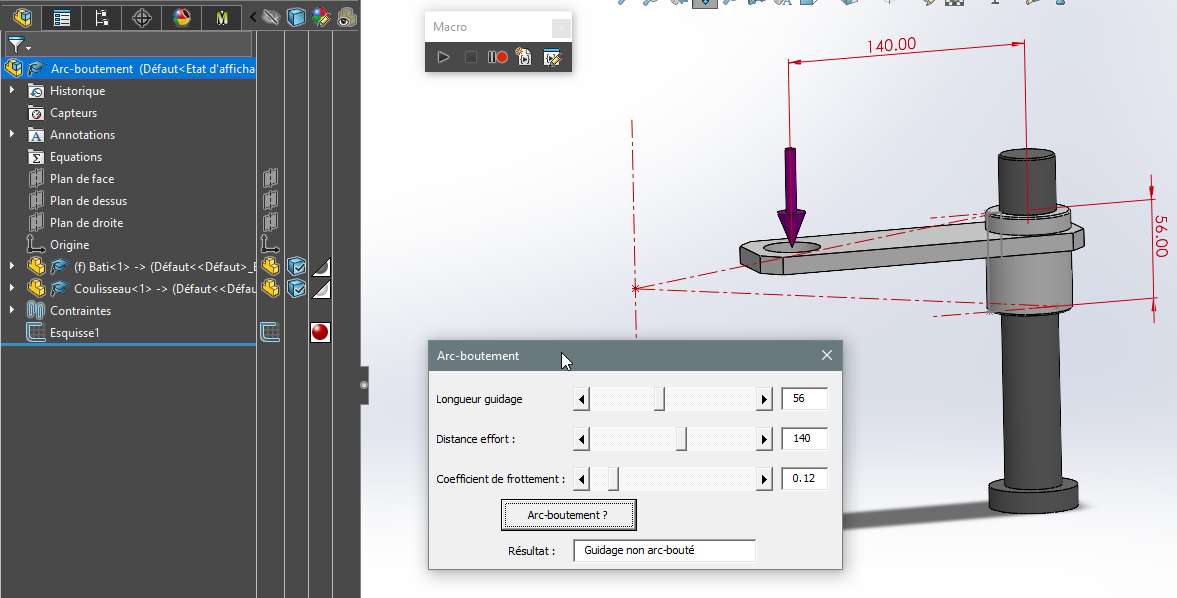
I'm going back to the thread of the discussion, you're right, the goal is to make a salesperson in my case understand the basic relationship: length of the ring guide (H), length of the maximum lever arm before butt arch (L), Diameter of the support pin (D). I'm looking to check by static graph L = H/ 2 x tan (phi) The adhesion coefficient phi. (0.2 for my example) ANNEX Non arc Buttement validé-1.pdf (1.5 MB)
So having a Boolean is enough because the concrete application is to have the information. Thank you for the process to follow or guide me on the steps to add. On my side, the idea is to have equations and allow me to reconstruct without going through derived configurations because I lose violent geometry relations... a tangency is OK when recording but when opening it is 180° (with the box checked in the dialog box without my intervention, it's satanic...). Same with a perpendicularity orientation, I have a bug when opening.
I have a little trouble seeing the link that exists between the risk of buttress of the guidance and the tangency/perpendicularity constraints mentioned in your message.
The relationship you use in your theoretical study is the so-called " clamp " relationship, which validates the fact that it remains blocked under the effect of the tightening force. Judging by the illustration in the pdf document, it is more of a mechanism in which a translationally guided ram probably has to move in both directions. If the weight contributes to the sliding motion of the slider, there must be a " motor " element to raise it. The risk of buttresses also concerns this element...
The attached document (SW 2021) and the accompanying macro illustrate the " clamp relationship" by acting on the length of the guide, the distance of the force to the axis of the guide, and the coefficient of friction. With a single column guide... To adapt it to your model, you will have to modify the names of the dimensions and parts that are used in the macro...
This is exactly what I wanted to be able to highlight, for the constraints it is an instability of the solidworks software which with my unsuitable use for the opening I have tangency constraints that are reversed between two constrained elements*. No relation to the case analyzed here.* Thank you for the work done, I will take my time tomorrow to analyze and understand the structure of the macro. What's very nice is to have cursors, last week we were wondering how to have a control in solidworks other than with equations. I worked in a group on the control of 3D models from sketches by introducing equations with ifs, it's not bad it avoids going through configurations or creating a family of parts, disadvantages remain but it's the practical implementation to see on models in the future. Very good end of the day, I have work to do to analyze the functioning of the cursor. Kind regards.