Hello
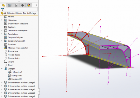
I try to smooth 2 sketches but nothing to do, yet when I extrude them independently it works.
I'm under Sw2013
I attach screenshots and the files
Thank you
Diiity
care.jpg
capure.jpg
capture.jpg
t4.sldprt
Hello
I try to smooth 2 sketches but nothing to do, yet when I extrude them independently it works.
I'm under Sw2013
I attach screenshots and the files
Thank you
Diiity
Hello @diiity;
Two proposals to achieve the expected result:
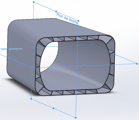
- the sketches appear symmetrical with respect to the x-axis and y-axis. It is therefore desirable to work on a quarter of the piece, then to complete by symmetry;
- The smoothing function does not allow you to have several loops in the same profile. It is therefore necessary to smooth the outer shape, then to remove it by smoothing for each cell.
An additional advantage: the sketches are lighter, therefore easier to constrain...
Kind regards...
To do the exterior smoothing, I simply selected the different lines and curves but it doesn't work, with guide lines
Good evening. A geometrically interesting piece but not feasible by traditional manufacturing methods. I know, that wasn't the question but maybe that's the reason why the software fails. The two sketches to be smoothed are similar but not enough for the software. It cannot connect the two surfaces by a single operation.
To choose the outer contour, you must use the closed loop (not the segment group). This will select the closed outline.
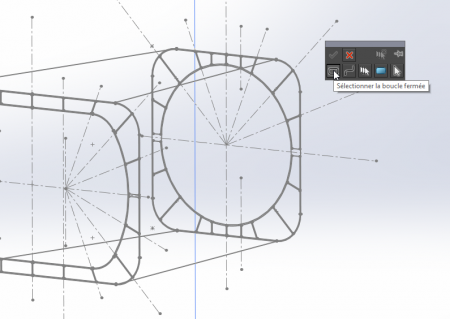
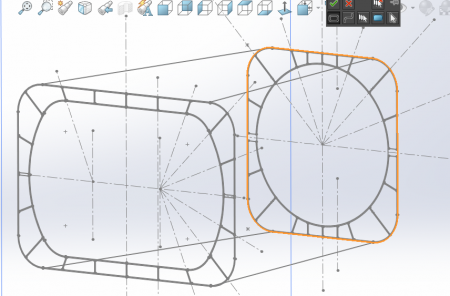
then to remove the interior volumes, make smoothing removals by selecting the regions.
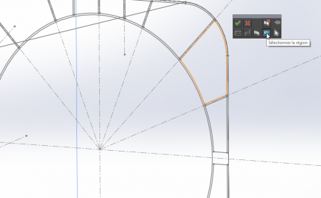
The guidelines are not useful for this smoothing. The double symmetry is well justified by the previous answer of m.blt.
Hello
Great it works.
My concern is to know to whom I attribute the best answer...
diiity
Hello
Symmetry lines correspond to tangent face connections. To view/delete them, follow this path: Tools > Options > Display in the System Options page, then choose the checkbox that suits you in the Display tangent edges box.
Note that the property will also apply to the other tangent faces of the part if there are any.
Have a nice day.
For partitions, would the repetition driven by a sketch of a thin function supported by 2 composite curves corresponding to the inner and outer walls work?
In this case, the symmetry lines cannot be removed. Normally, stitching surfaces in the symmetry feature removes these junction lines.
The solution is to make successive smoothings.
First of all, the exterior volume
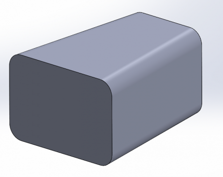
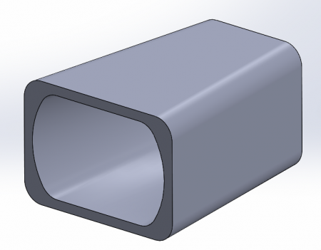
Then subtract the central volume by smoothing material removal
Then the same function for each recess on a quarter of the part

And finally
the two symmetries of these recesses.
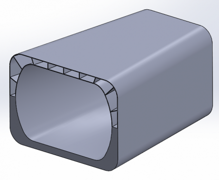

Nine functions in total
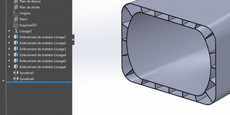
Last question.
I managed to hide the symmetry lines but depending on the zoom, the lines of the cells are visible on the top but if I zoom closely, they disappear
Hello
Concerning the symmetry lines, I am of the same opinion as @soring, normally the symmetry function removes them (merge, sew surfaces),
For the zoom problem I suspect the facetization,
Hello
Generally speaking, the symmetry with respect to a plane of a volume or surface function reveals an edge at the connection. This is even if the surface ends up on the plane, in a normal way, which is the case on the part proposed by @diiity .
The "deviation analysis" shows that the deviation in the orientation of the normals at the connection edge is zero, at least to the second decimal place (see attached video). And yet SolidWorks does not combine the two surfaces into one and retains a visible edge, even when using the surface stitching feature. It seems that beyond the second decimal place, normals are no longer confused...
In contrast, SolidWorks hides the edge after selecting the ad-hoc checkbox in the "Display tangent edges" option. This confirms the almost tangent nature of the connection.
Exception: if the surface to be balanced is a simple surface - plane or cylinder of revolution - normal to the plane of symmetry, SolidWorks manages to confuse it with its symmetry, and the edge disappears since there is only one surface.
The way to avoid the presence of these edges on the "t4.sldprt" part: to generate the outer shape in a single function, without using symmetries, therefore with a single surface. The same goes for the central recess. And, icing on the cake, the definition of the part now uses only 4 volume functions.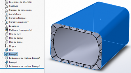
Appearance of hidden edges... Under certain conditions, theoretically hidden lines of the room may appear if they are located behind thin walls. This is especially the case when zooming in dynamically...
This is only a display anomaly, the topology of the part is not in question.
Kind regards.
Nice explanations, I thank you all for your contribution but I still have this concern to assign the best answer but you have to make a choice.
diiity