In a Solidworks BOM, is it possible to display several configurations of the same part under a single line?...... while continuing to display multiple rows for multiple configurations of another component.
Example:
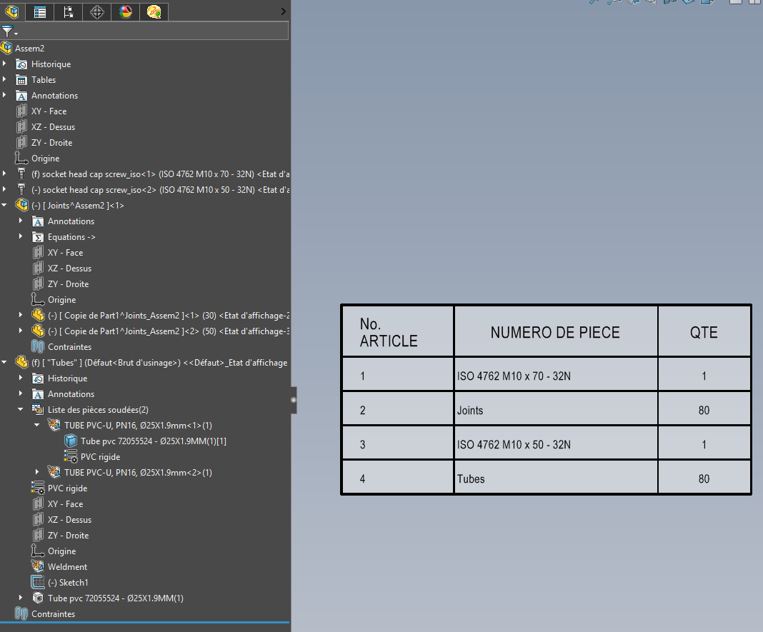
A set contains two pieces with multiple configurations (a CHC screw and a door gasket). The CHC screw will appear in several lengths, as will the door seal.
In the nomenclature, each configuration of the CHC screw must appear in different lines. On the other hand, the door seals must appear under a single line, containing the sum of the lengths.
Currently, we do this by hiding BOM lines, or by excluding components in the 3D. Then we write the sum of the lengths manually. Which is not a very elegant working method...
I have the same problem, we work in "parts only" I have parts that are machined straight and that are "twisted" during installation. So I created a bending function with a different angle for each configuration to have a correct 3D visual, but in the base part is the same so I only want one line on my BOM.
I also have screws that are the same but with configurations of different sizes and lengths and I would like them to be visible in the nomenclature.
I don't see how this could be possible either on detail, or on not detail but a solution between the 2. To force quantities and delete lines manually, impossible.
form a sub-assembly with a global variable equal to the sum of the length dimensions of the different configurations of the component (in the request for @sguillaume : the door seals)
-the simplest in my opinion- use the welded construction mode to create in the context the different lengths of the component (in the request for @sguillaume : the door seals) and include the " total length" property of the welded body in a property of the part to be used as Qty in the nomenclature.