I'm recreating a new post, because the previous one lacked clarity — sorry for that.
I regularly work on 3D integrations, in particular to position our equipment inside buildings.
For our technicians, it is essential to have an overview showing both the building and the installed equipment in its exact location.
To illustrate my need, let's take a simple example: I want to model my house (the building) and place my sofa on it, indicating its dimensions and position in relation to the wall.
I only want to see the overall volume of the sofa, without the internal details (springs, slats, etc.).
My goal is to work with a building represented as an envelope — that is, a volume of which only the outer walls are visible — so that I can easily visualize the objects placed inside.
In concrete terms, when I integrate a machine into AutoCAD, I would like to be able to see both the wall and the machine, without the wall obscuring the visibility of the machine.
Do you have a solution or method to recommend to me to obtain this type of rendering?
I don't want to use the visibility of hidden edges, as it makes it very difficult to read and clear the shots.
If I understood correctly (without an image difficult to be sure), You want to draw a filled cube for your building and that what you gill inside is not a hidden line? For me this is not feasible (nor logical) for Solidworks.
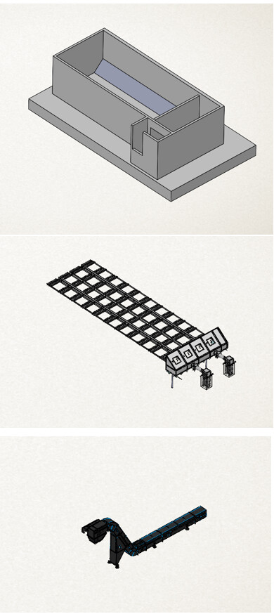
In general, for a building, it is enough to represent the thickness of the walls, to open the front wall and the ceiling and voila, for a clear plan with a positioning of each thing in relation to a reference (here below the corner at the back on the left). Example:
Another method is to make walls in surface so as not to represent a wall thickness (or wall that we don't necessarily know.
If I misunderstood, show us an example in pictures of what you get and then explain what you would like, to be clearer and avoid a 3rd post! On this subject it is easy in a post to add additional explanations and easier for the people who answered it, to follow the thread.
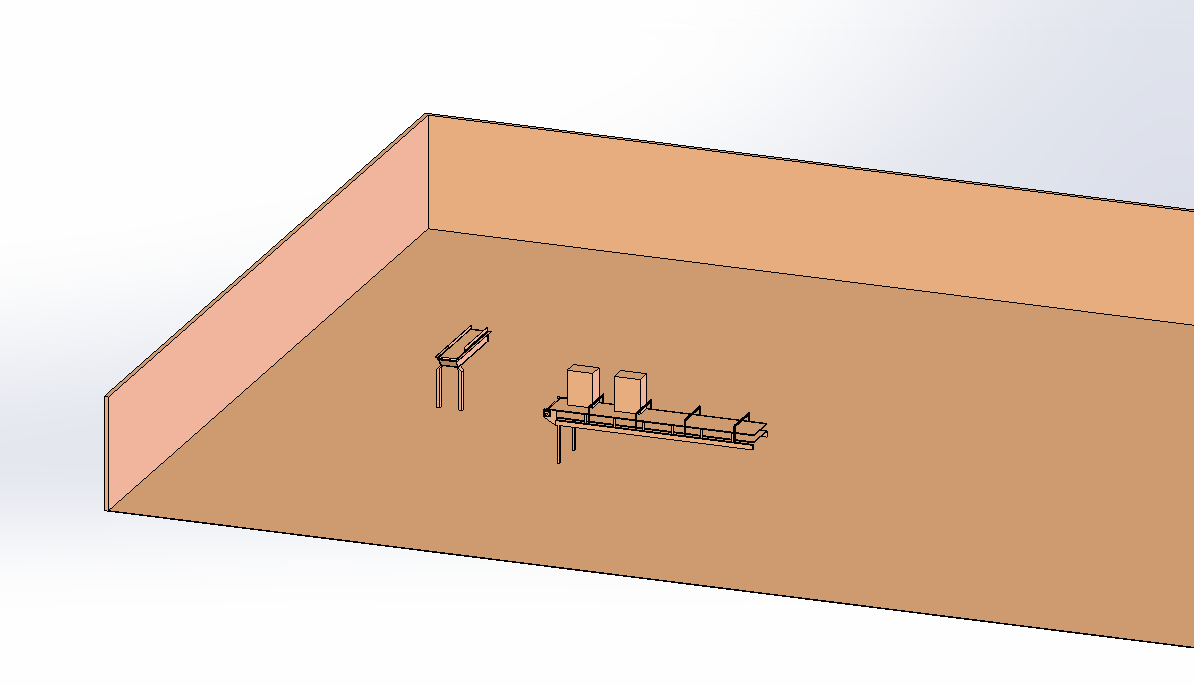
I've never tried with surface, maybe it's a good idea. Here, in pictures, is my problem:
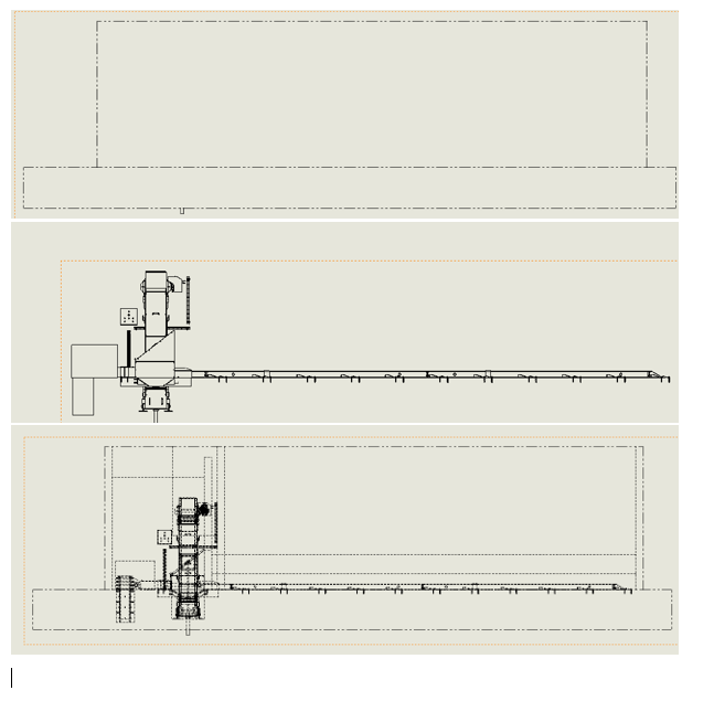
I integrate several systems in a building. I don't represent the rooftops, but I need to display the walls.
On this setup, it's pretty light, but if you don't go through a sectional view and change the display style to apparent hidden lines, the view becomes really overloaded.
I wish I could stipulate that the envelope coin doesn't go ahead of the others.
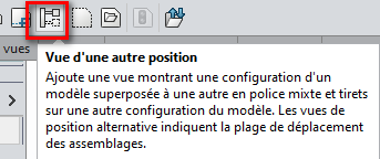
Have you tried with the " view from another position " option in the drawing? => In the assembly, the building is removed from the " default " configuration => A new configuration is created in which only the building appears.
In the drawing, we create the views of the " default " configuration and then for each view we add the " Building " configuration with the " View from another position " option.
For me the most understandable in this case is seen from above and then systematically cut, so as not to see the wall.
SW won't know how to do what you want. All the other methods would remain DIY for me. Style: make a config without the front wall for one view and not for the other... The surface will create the same problem for you (or apparent or not, and no intermediate solution) Edit: the @Maclane solution (seen from another position with the building might actually meet your need with dotted line in the background.
Thank you for this feedback, I will try this solution. I take this opportunity to ask you what your drawing options are when you do a large installation, it is often difficult to select edges etc.
In no case do you recover a drawing on which there have been cuts (they are never deleted from the Solidworks memory even if the view is Deleted...
Maximum info for a minimum of views.
No excess ISO views.
As far as possible, we avoid mixing " color " views with Black-and-white views...
Tangent edges are removed (unless it interferes with comprehension).
We reactivate the " Dynamic Graphics View Highlighting" option in the system/Display option when it is disabled for no apparent reason (this often happens)
We use our own Drawing Standards.
We try to keep our basemaps and our Layout templates up to date. … => And of course we regularly empty our directories *.Temp. + Using Solidworks Rx to clean up the rest...
I almost forgot: We disabled Solidworks' autosave (it was almost impossible to work with the active option, by the time our assemblies opened, solidworks was already trying to save them => Vicious circle / Cyclic redundancy).