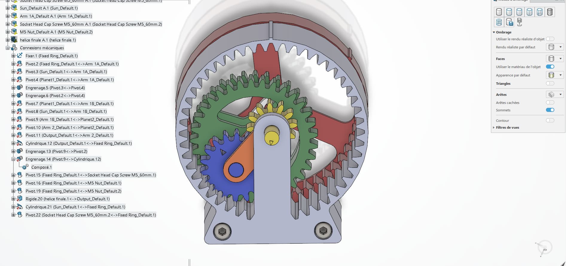
Hello, I created this planetary and then I added all the mechanical connections but I'm not sure if the gears turn in the right direction, someone can tell me in which direction they are turning in relation to the others to see if my simulation is good Thank you for your answer
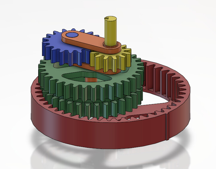
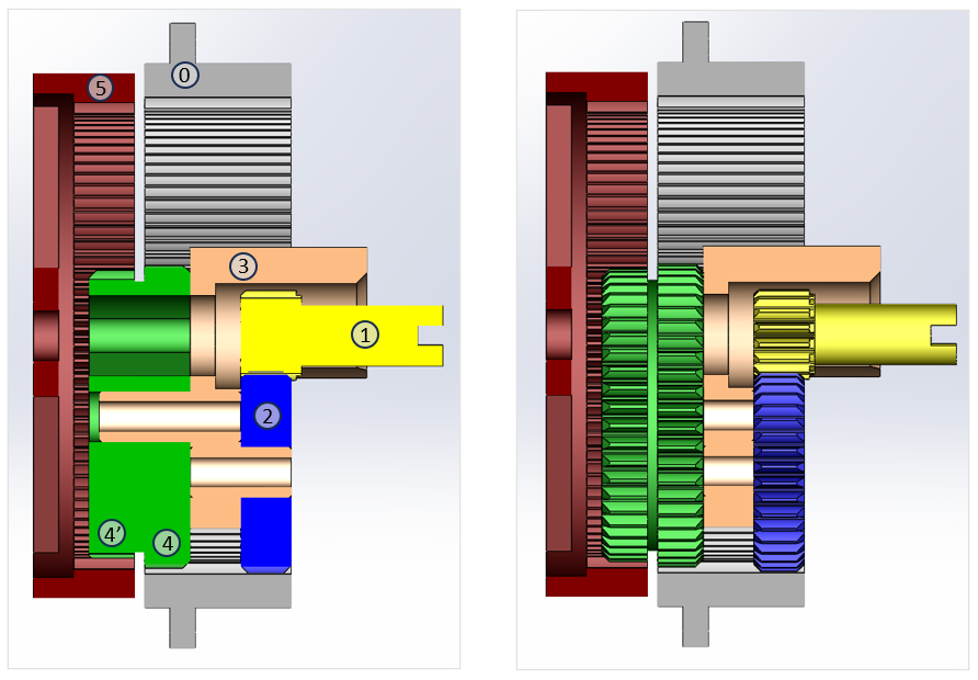
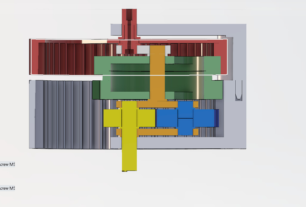
What is pretty much clear on the images offered... It is a gearbox with epicyclic gear. The entrance to the first reduction stage is the yellow planetary which meshes with the blue satellite, itself meshing with the grey fixed crown (frame). The output of this reduction stage is the orange satellite carrier.
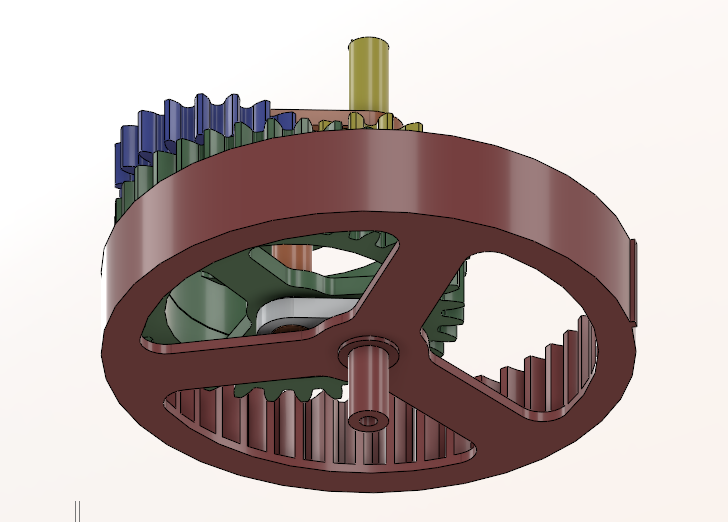
What is less clear... The rest looks like a second epicyclic train, but a few data would have been a great help. The two teeth of the green satellite have slightly different numbers of teeth, as well as the teeth of the ring of the frame and the red output planetary. The result is a very high reduction ratio: train by Onésiphore Pecqueur (1792-1852). You have to be very attentive to observe the rotation of the output crown on the attached video.
A suggestion: in the future, attach the SW assembly to your request, it will be easier to offer you an answer. What's more, it's exactly tailored to your model.
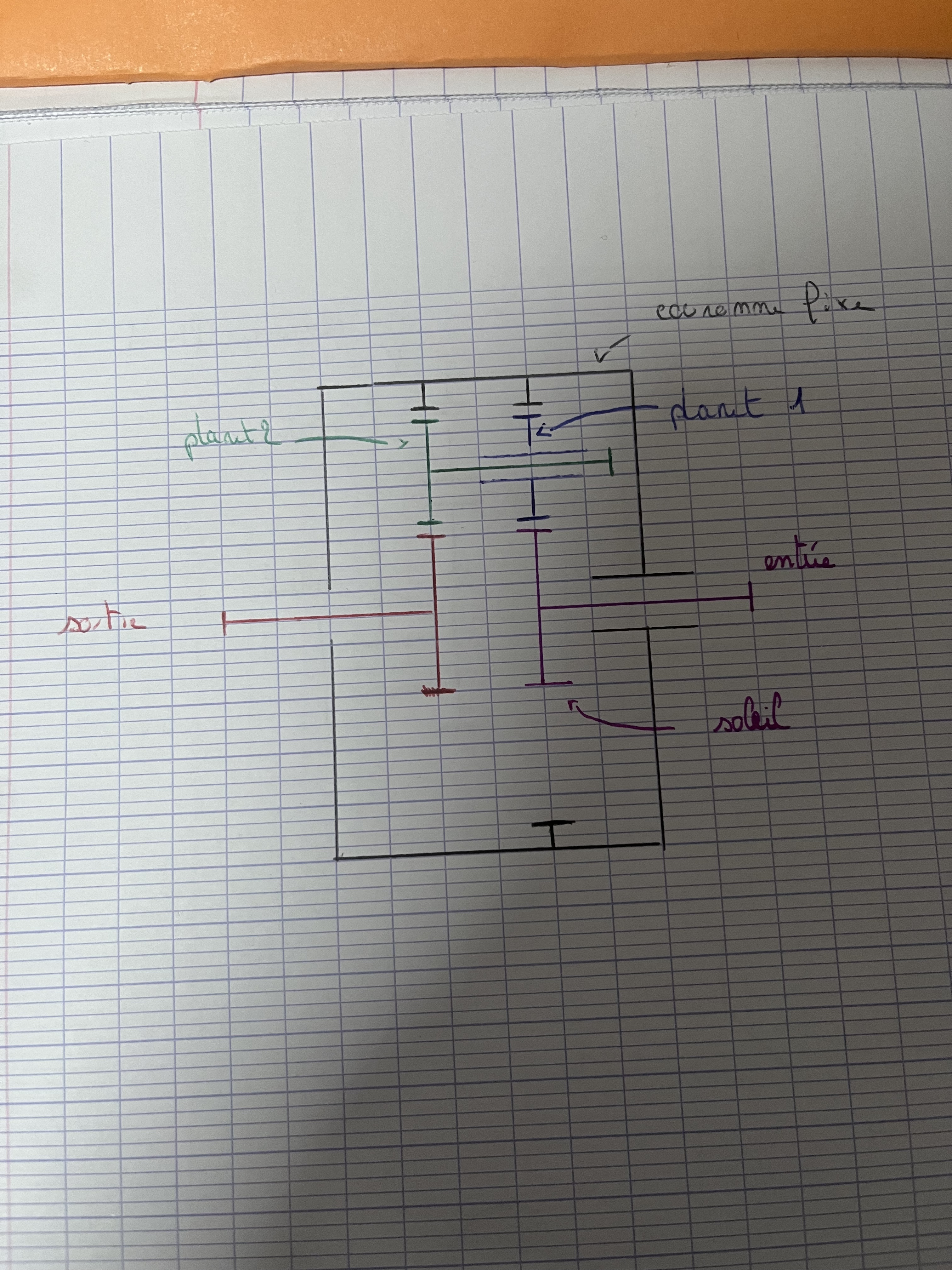
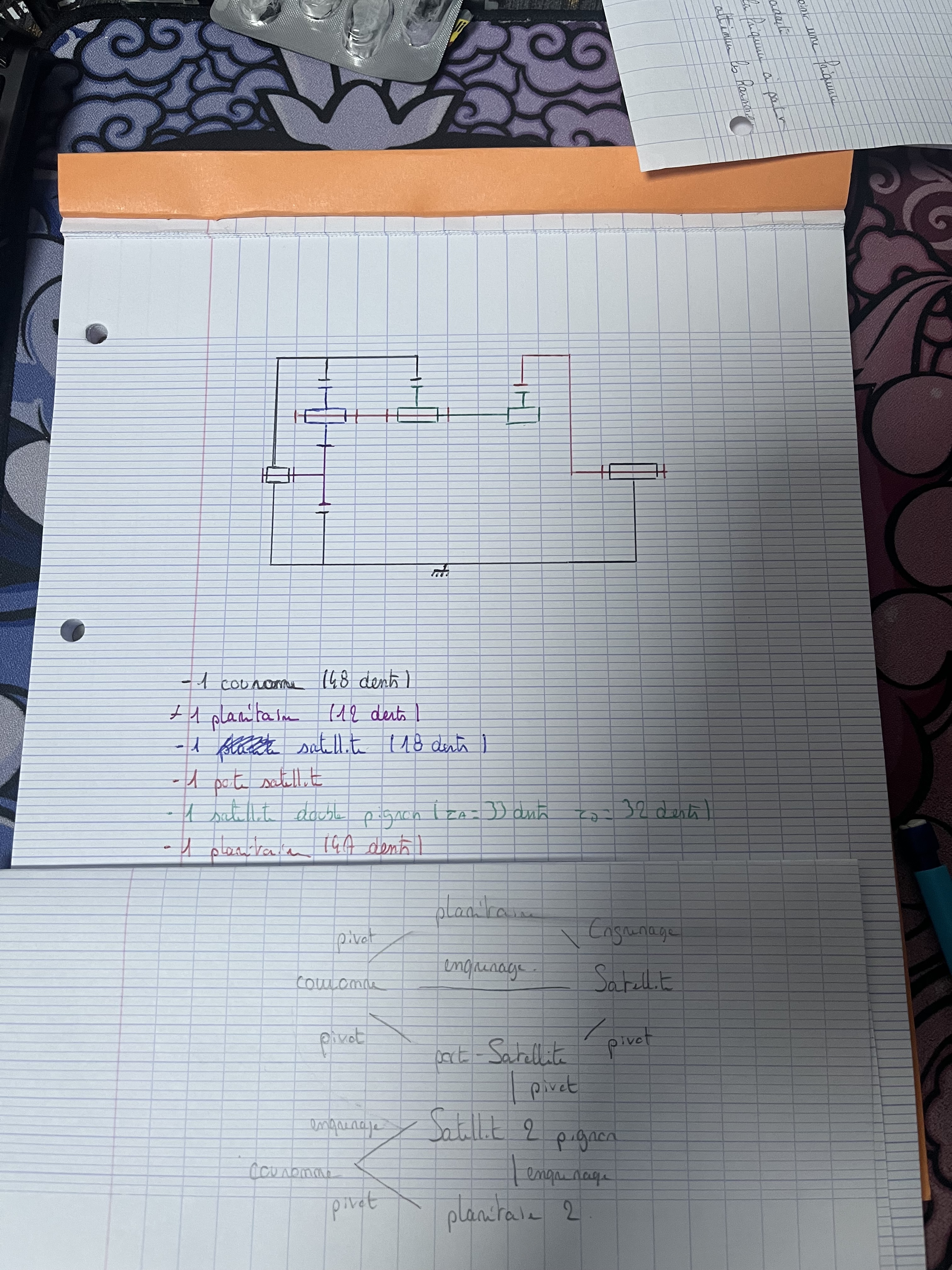
@m_blt Thank you for your answer, I was limited to 1 photo per message so I didn't even try to send a video . I have another question about this system, I have to make a kinematic diagram of it but I have never had to deal with a 2-tooth satellite, I made this diagram (see photo), can you tell me if I'm wrong, and if you know a good site to model this kind of diagram I'm interested Thank you again for your help Good night
OK for validating a schematic proposal, not to do the work for you. The one in your photo is too imprecise and far from the structure of the gearbox to be commented on... A few tips:
Observe the SW model, in section and in external view, to identify the kinematically related subassemblies. Be careful with the names: the sun is not a common name in an epicyclic train;
to find out who is linked to whom, as well as the nature of the contact areas, and therefore the links. Not all of them are materialized on the SW model;
Diagram in a " wire " representation, in color, by locating the relative positions of the connections in a well-chosen marker. Not too complicated here...
On the diagram, or in a table, or better on a structure graph, show the primitive spokes or the number of teeth of the cogwheels.
For the graphic tool to be used, the " Shapes " module of Word seems to me sufficient for such a 2D diagram, with the advantage of being easily integrated into a possible accompanying text.
@m_blt Hello again, thank you for your answer, I reviewed my diagram I propose the following what do you think? I added a diagram explaining the connections (I put 2 crowns but it's the same, I put it for a little more clarity) as well as the data on the teeth I have. Good night
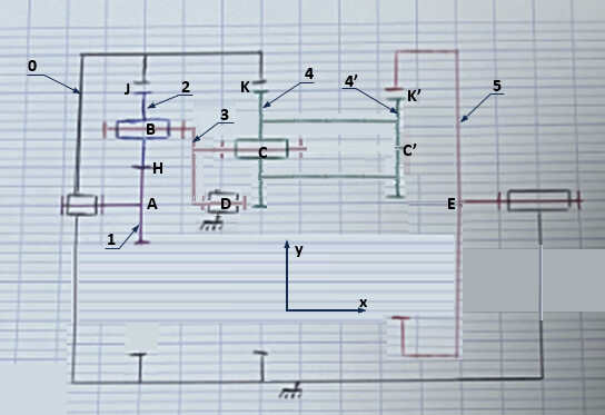
Hello Clear progress in this proposal, except for the visual quality of the document... The structure graph defines the right number of parts, the number and nature of the bonds... In terms of the diagram, the structure is generally correct, except for the satellite carrier (what you call " arms 1 and 3 "?), which is nevertheless a central element in an epicyclic train. It is the absence of its pivotal connection with the frame, on the same axis as that of the entrance gable, which is the most glaring lack of the diagram. Another inaccuracy at the level of this satellite carrier: it intervenes in the first stage of the gearbox, located on the left, but also in the second located on the right, with different spacings in the two cases, which does not appear on the diagram.
On the hacked image below, I made the changes that seem essential to me... Make the best use of it...