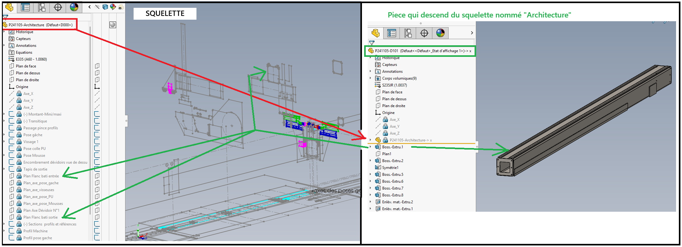
Hello On the use of the Skeleton method, what is the right method to take with Solidworks? How do you design your parts so that they depend on your skeleton? Since apparently integrating the skeleton into the part is not reliable...? (subject mentioned in another exchange, launched by FRED78 - " update of a derivative part in another part ") For my part, I use this method, to insert my skeleton into a room, but I have big crashes, and parts that become corrupted and unusable, I have about fifteen to start from scratch... Here is the method in pictures:
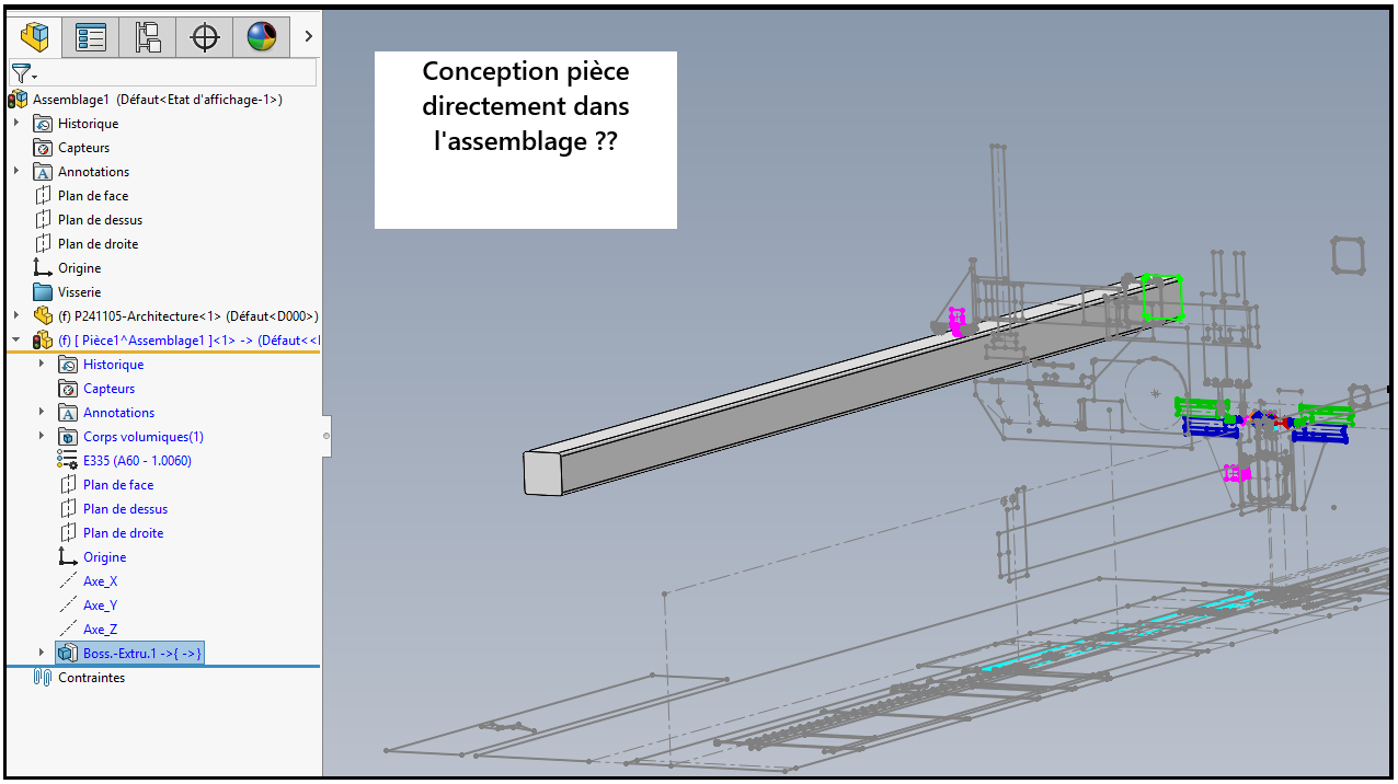
OR, should you design your part directly in the assembly, by converting the entities of the skeleton?
Note: what I had done in the meantime to try to get around my crashing problems: Since my skeleton is finished and I'm not going to evolve it anymore, I just want to use it as a " layer ". So I put it on the server as read-only (so that my colleague and I could use it at the same time). And in every part I've designed, I've inserted this skeleton, and to avoid having potential problems with reconstructions, I've broken the links to external references, and locked the import of the skeleton. This approach is not normal, since IF I want to evolve my skeleton, the parts will no longer follow, you will tell me... but I do all this to get around my untimely crashes... I'm looking for solutions to work serenely (without the sword of Damocles waiting over my head.
So please, what is the right method to design and model your parts on a skeleton?
The skeleton method is a good method, but from the images posted I have the impression that you are already going too far in terms of the amount of information in your skeleton.
Also be careful with the breakage of the external refs. Prefer "Lock references"→ this allows you to better control the update of external references.
A variant to the " Insert Part " function for skeleton-based design exists: sketch blocks. It is possible to link a block to its source file. Personally, I have never used this method before.
To fully state my point of view: There are 3 main design methods:
Bottom-up design
Top-down design
Master Model
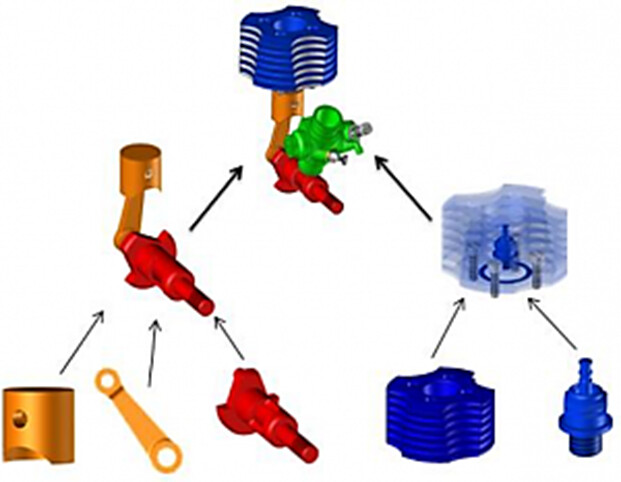
BOTTOM-UP DESIGN: Principle:
Individual design of parts without external refs Subsequent assembly for product construction.
Advantage:
Flexibility
Reuse of components,
Parallel workflows,
Component optimization,
Simple and robust SolidWorks implementation (no external part numbers).
Disadvantages:
Longer,
More tedious (including for the control of modifications.),
Configuration management,
Requires more thought to ensure assembly,
Lack of overall design control.
TOP-DOWN DESIGN: Principle:
Definition of the constraint (environment, skeleton, set of parameters), to deduce the geometry of the components.
Advantage:
Easier design by basic sketch (skeleton)
Disadvantages:
Understanding design intent
External relationship / referral management,
Configuration management,
(Very) slow reconstruction → rebuilding a feature may require rebuilding all parts of the assembly.
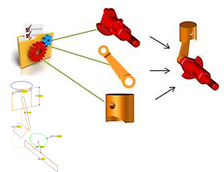
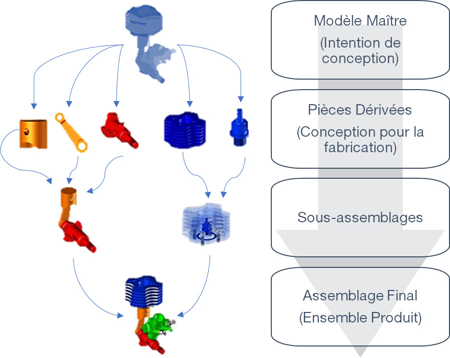
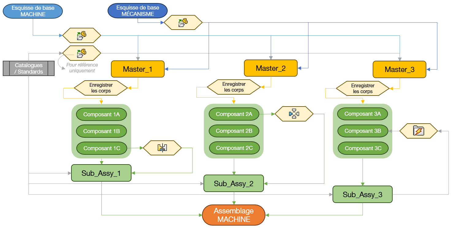
MASTER MODEL DESIGN Principle:
Capturing the design intent (shape, size) of a system in a single part (master model);
The bodies are then copied to separate parts files (derivative parts) to generate the components.
Advantage:
A single file to define the system
No relationships/references to manage during the ideation/conceptualization process
Faster design with reduced errors and interference
Quick Edits
Disadvantages:
Complexity
External Relationship Management / Referrals
Collaboration
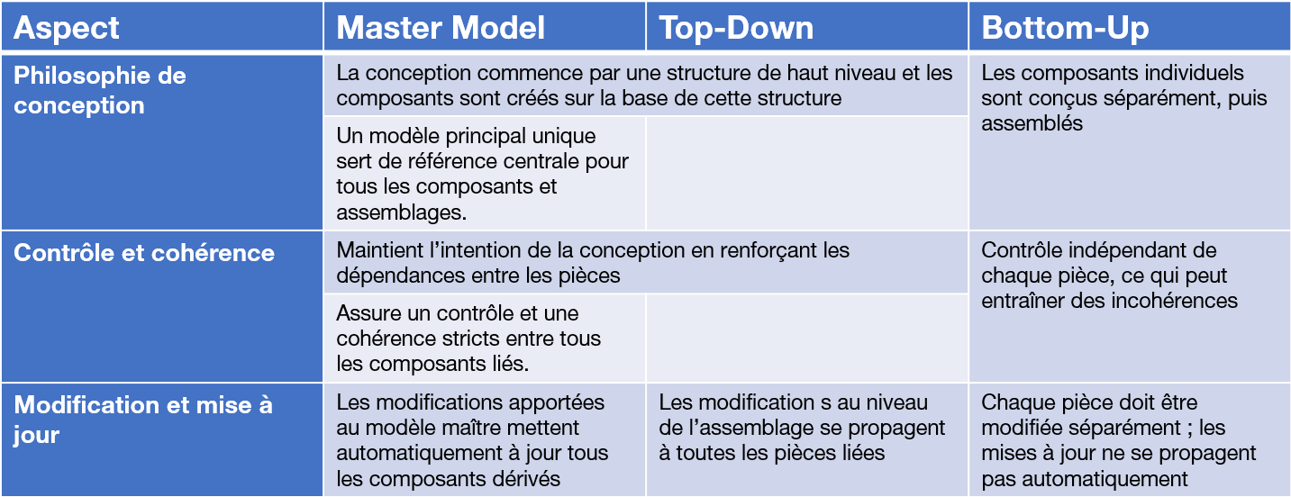
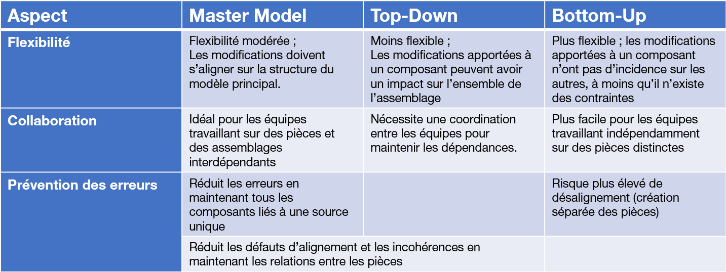
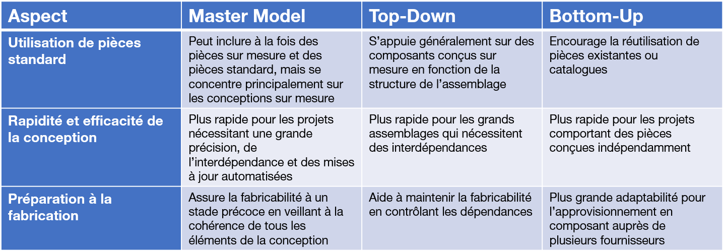
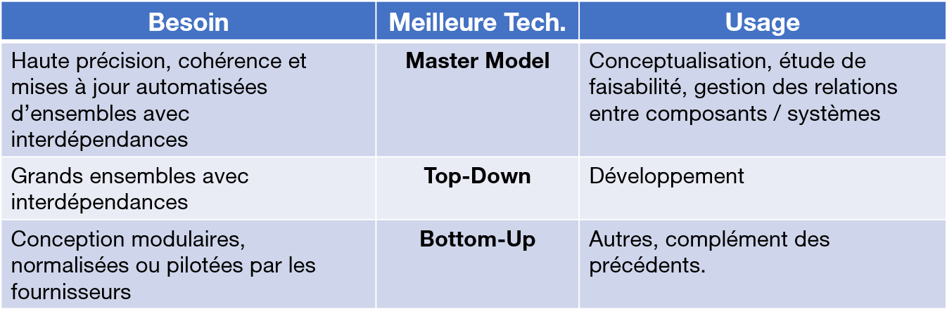
Comparison of techniques:
In short...
Knowing that with machines, we have a bit of the 3 needs, we have to mix the 3:
I think both methods are good. But you have to set up SolidWorks for the derived part (Skeleton) to update The problems I encountered with this skeletal method are visual problems at first. That is to say, the sketches at each update are shown in each room (Also true for plans & Axes).
In the case of the method with the design in an assembly in external ref. Personally I prefer. It's easier to see if the cartoonist has worked rigorously. I didn't see any particular problem, from memory. The only problem we had was on a particular position of a service provider, the problem was that he lost external links, for no apparent reason. 3D experience or other, One drive, I don't know what software was screwing up... . We solved the problem with a non-connected restricted PC Fixed license, and problem solved.
In any case if you use these methods you have to use it all the time, never make an element without it. And be very rigorous. The advantage of these methods, in addition to sharing common coordinates, is to create assemblies dedicated to drawing. But that's another story
And in any case, both methods have their advantages and their defects
Hello to you, OK, thank you, I'll take the time to analyze all this. @Silver_Surfer ; I would like to come back to what you tell me, " you are already going too far in terms of the amount of information in your skeleton ".
Why do you think I'm going too far?
For me, it is my overall environment of the machine that I have to design, with its different workstations that are dependent on each other. The goal is that each of my collaborators can develop their sub-assembly, linked to this skeleton, and that I can bring together all the sub-assemblies in 1 global assembly which will be the machine. Everything starts from the same origin, everything evolves according to my skeleton. If I have to extend the machine, to add a station, I just have to modify the skeleton, and everything is updated. I have already seen much more complete skeletons than the one I am presenting to you, where there was the complete environment of a company, with all the conveyor lines, and each employee worked on 1 workstation, and the project owner updated the overall environment of the company at the end of each week via this skeleton. That's why I'm surprised when you tell me that I'm already going too far, for my part I don't think there's much...
Going too far in this method I don't think the opposite. You should always use it. Because the purpose is not only the common coordinates between all the parts and the actors of the project, it is also reliability and defining a single source of design in a CAD assembly. But the useful and specific purpose of each is the assembly dedicated to the drawing, containing the sub-assemblies originally fixed (=reliability). This assembly allows you to realize all your needs to realize your plans. It is possible to remove materials, configurations, etc.
Please note that 3D modifications are preferably made in the design assembly, and always in the context of the part and its sketch and function.
The advantages: Stable study assembly because only one method is used Control of working time, depending on the size of the assembly Reduced weight of the study assembly: - no constraint, or very little - no configuration apart from the screws elements or exceptional case in the design assembly. Nomenclature more easily achievable. Ability to insert environmental elements into the design assembly without weighing down the design assembly.