Simulation: assembly contact vs. component contact

Hello
Still in my discovery of simulation, after having done the tutorials, overall I grasped the main lines of most of the steps but I have trouble grasping the conceptual differences between "contact between sets" and "contact between components".
There are more or less the same contact options ( No Penetration, Solid, Allow Penetration, Tight Fit, Virtual Wall.)

I found this answer (https://www.lynkoa.com/forum/solidworks-simulation/propertymanager-contact-entre-composants-ou-ensembles):

Les "contacts" permettent de définir certains critères de maillage et de déplacement des pièces entre elles. 
Tu as les "contact entre composant" qui te permettent de sélectionner des composants entiers de même type. 

Which leaves me a little hungry.

Knowing that at the beginning we already define a global contact on no penetration by default, it seems to me (I am mainly interested in the "classical" static study).
Is the type of components (solid, shell, beam) the only criterion that determines the choice of one or the other when we want to specify a contact ?

Thank you

  Hello Stef

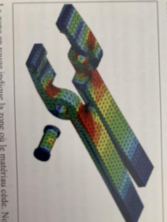
A set is, for example, a blacksmith's pliers. The assembly consists of two arms with an axis between the two

So at the beginning the clamp is slightly open or closed and you have a contact between the axis and the two parts of the clamp.

If you put a moderate force on the arms, you will have two effects: the tightening effort will increase and you will see it in the result, a certain flexion of the arms

The two small levers of the clamp will touch each other to clamp the part but as you have put a contact without penetration, if you continue to put a lot of clamping pressure the two arms of the clamp will, after exceeding a certain flexibility, end up touching.

This is where it makes the difference because you then have a late contact between two sets.

A simplified assembly is an arm of the clamp and the "contact between set" is the contact between the two arms.

In the courses they take this simple example of the clamp but if you take two assemblies let's say mechanically welded complex then each assembly is indeed a set (meaning parts forming an asm).
But you, as a designer, know that these two sets can end up touching each other and obviously, in real life, the parts cannot interpenetrate each other, you define that there can be a contact between these two sets (typically a stop that limits a bending).

Why SW makes this distinction
1°) because at the beginning there is no contact between the two areas of the two sets so you have no other choice to say to SW "my pot' calculation for me" the moment when these two sets will touch each other and knowing that they will not be able to interpenetrate each other.

2°) it is necessary to activate in these cases the choice "large displacements" Indeed, the system calculates the displacement by iteration and if it exceeds a certain value it will stop the calculation considering that this displacement is too important. If you put a lot of displacement, it will tolerate a higher displacement (but which remains within a certain value). Very useful in the case of mechanically welded frames or softer materials such as aluminum or bending can be important in a natural way.

3°) It is also in this case that the choice "no penetration" is understood and takes on all its meaning, because the two pieces are not in contact at the beginning. Note that most beginners (I was one) check "no penetration" while their assembly is without play: that the two pieces touch each other with a normal global contact and that there is no movement of sets. In most cases, the "no penetration" choice is superfluous as long as there is normal play.

@m.blt will surely complete my remarks with other examples and explanations.

Kind regards

simulation_entre_ensemble_vue_1.jpg
simulation_entre_ensemble_vue_2.jpg
2 Likes

 @stefbeno

to simply answer your initial   question "contact between assemblies" and "contact between components".

A set is several components, typically an ASM with several components (several parts). For example, a small welded frame made up of tube components or a pneumatic cylinder with all these components.

Here, we will decide that your ASM is actually a subset. So you can make bending simulations of your set but with contacts between components.

But if you have a super ASM with, for example, two sets (two ASMs) that have nothing to do with each other, then you will have contacts between sets. Knowing we agree that simulation will compute each of the sets and also simultaneously the interactions between the sets.

Say otherwise

an isolated ASM = contact between components of this ASM

Assembly of 2 or more ASMs then = Contact between assemblies meaning contacts between ASM  
ASM  = assembly = assembly (assembly = things put together)

Kind regards

PS: together we will achieve this through Lynkoa-ian contacts

1 Like

Hello

If you manage the contacts between components, it means that component A cannot interfere with component B.

Between sets: you specify the management of the contact between certain surfaces only. So in the end it's much faster (intuitively you know in advance where the contacts are going to take place, SW is quite stupid so he will check that ALL the nodes of the 2 parts do not come into contact if you choose component -> much longer calculation time).

To optimize contact management you can use the "separation line" tool before doing your calculation: it can allow you to reduce the surfaces of the contact areas and therefore will allow you to speed up the calculation even more.

3 Likes

Hello @froussel 

Thank you,  indeed I should have specified for the "separation lines" to better target the contact areas.

Especially since I made a tutorial on separation  lines (MDR) and that regularly recommends their use for simulation (see the tutorials on simulation)

Kind regards

Thank you for these first elements.
Yapluka test...

I'll be back

1 Like