Hello
Attached is the SW 2020 file of the crown, I made a simulation - see attached image - but I'm not sure of the result.....
with a torque of 180 daN.m
Can someone help me see more clearly?
Thank you in advance
couronne_cr_65_dents_courte.sldprt
Hello
Attached is the SW 2020 file of the crown, I made a simulation - see attached image - but I'm not sure of the result.....
with a torque of 180 daN.m
Can someone help me see more clearly?
Thank you in advance
Erratum: 150N.m TORQUE!!!!!
ALU 2024 - 0
Is there nothing anyone can do?
Not the tps maybe!
I'm waiting
Good evening @pierre32.debate
Some small problems
1°) you have not attached the results of your simulation so we cannot say anything about the parameters used (make a pack and go with the addition of the simulation results)
2°) you have an error on the main sketch of your chain sprocket (invalid geometry length ?????)
3°) Looking at the image something seems strange to me (to be confirmed with the reading of your parameters) but I have the impression that the loads are not correct.
4°) Are you sure of your relationship (it doesn't seem like much)
5°) what is the difference between the torque at start-up and the torque at 5000 trs.mn or more
Conclusion: Quickly a pack and go Zipped which is less difficult than climbing an impossible slope ;-)
Hello
The "static" modelling is clearly not representative.
As it is a chain transmission, there are no more than half of the teeth that work (a priori much less) and the effort will mainly go through the first taut links (and the associated teeth on your part).
Ideally, you should have an idea of this distribution of effort and apply these decreasing forces to the first 10 to 15 teeth.
As a first approximation, you can put all the effort on a tooth (it may hurt...). It may be necessary to restrict the surface to apply the force (the top of the tooth does not see any force for example since it is not in contact with the chain at all). From what I have just read on the subject, this approximation seems to be retained most of the time.
Personally, by applying 920N on the complete rounding of a hollow of a tooth (150Nm / 0.163m tooth/axis distance), I find 26.59Mpa of constraint which is not huge far from it. It was on a tooth that is in front of a reinforcement so clearly one of the most rigid.
Reading if you want to be more precise on the application of forces on each tooth: https://orbi.uliege.be/bitstream/2268/148450/1/elmachopt.pdf
Good luck
Thank you for your answers,
Indeed, there are many parameters to take into account..... the action of the couple on how many teeth.... I am thinking internally to bring you more elements and to send you the simulation studies I have done
See you soon
PS: the crown is already made!! ! Will she resist?
Good
I can't find what's wrong in the sketch of the boss - I made a 1st crown that I sent for the milling machine and it was modified, hence the error occurred.... brief
then for the torque it is not 150N.m but 180daN.m and its action on half of the total dentition, i.e. 65/2 let's say 32 teeth
I attach the SW 2020 file of the crown where I found an error but not the rest, arrrffff
To be continued tomorrow
Thanks
Hello @pierre32.debate,
Quite a few points agree with @froussel, especially on the fact that the number of teeth actually stressed is much lower than that of the teeth "wound" on the toothed plate. I still took a slightly different point of view: known torque applied to the hub, locking at the teeth.
The hypothesis retained: too large diameter of chainring, too large tooth pitch, too many teeth, it's probably not a bicycle crankset, but it's similar enough to be inspired by it, for lack of more information. Maybe a motorcycle...
- the motor "torque" is exerted on a star hub with 6 pins engaged in the holes of the plate;
- The guide is made by a pivot in the central part of the hub;
- There are a little more than half of the teeth on the left side of the chainring that are in contact with the chain links. But only a few are at work...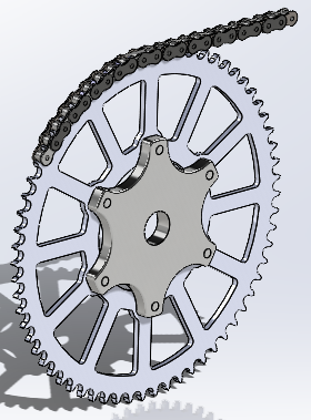
Translation into the finite element model:
- For simulation, the chainring is inserted into an assembly that also includes the hub and some chain links.
- All components are made of steel, probably not the right grade. But the orders of magnitude of the properties are more or less the right ones, apart from the limits of resistance.
- The default contact (global contact) between components is set to "non-penetration". As a result, the different elements are free to slide at the level of their contacts.
- A particular contact between components is defined as "solid" between the hub and the chainring, which are therefore totally connected.
- A pivot-fixed connection (imposed displacement) is created on the hub bore. At this point, only one degree of freedom remains in rotation for the hub-platter assembly.
- the "motor" torque of 1800 Nm is applied to the external face of the hub.
- 3 links are positioned and constrained in the tooth hollows in the upper part of the chainring. The overall contact without penetration allows the relative movements of the links between them and with the platen. The number of links is limited to 3 (i.e. 4 rolls) so as not to make the calculation more cumbersome. It is likely that these first rollers are the most stressed, and that the load decreases rapidly along the winding of the chain.
- To immobilize the rotation of the platen, an imposed pivot-fixed displacement is applied to the bore of the first link of the incoming strand.
- Also for reasons of speed of calculation, the mesh used is quite coarse (default values).
As micro-displacements exist between the different components, the calculation uses an iterative method that penalizes the speed of resolution. It takes about 2 minutes on this "light" model.
Once the model is perfected, there is nothing to prevent you from refining the mesh, and adding links to the chain. No doubt it would be necessary to go up to 8 or 10 teeth in grip to judge...
Below is an image of von Mises' displacement and constraint fields.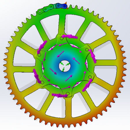
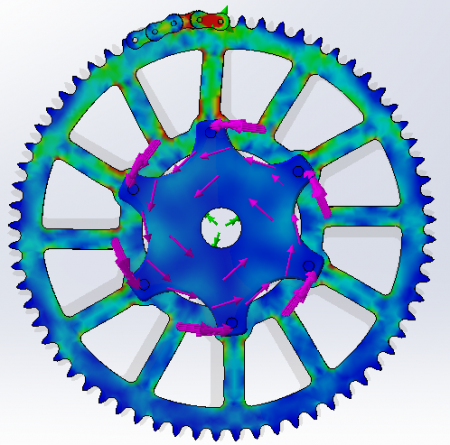
One last point: first 150 Nm, then 1800 Nm... This implies a chain tension of 11 KN, and a safety factor of just over 2 with respect to the breaking limit of a steel chain (DIN 8187). Coef 4.5 for a motorcycle chain (525 DID ZVM-X).
Kind regards.
Hello and great thank you,
Yes, the elements I provided, especially the 1st torque 150N.m is the engine torque at the vilo, then a cascade of gear ratios, hence the 2nd torque calculated of 180daN.m, also the engine runs at 10500 rpm +-1000 following
Carburetor adjustment, with competition petrol and electronic ignition too, by the way on this subject we were surprised by these 10500 rpm for a twin-cylinder with pistons of 90mm in diameter and 79 mm of travel..... Very good 2t oil needed......
The crown is centered on a shoulder of the hub which is also made of aluminum. As for the forces on the teeth, if the manufacturing precision is maintained, all the teeth that receive a roller of the chain must be stressed, in my opinion, with an equal distribution unless there is an excessive elongation of the 1st links..... also the grip of the wheel comes into play....
You have done a remarkable study-simulation work - very close to reality I think - I thank you very much for that, as well as SOLIDWORKS - what a tool!! - and the LINKOA forum is still as competent thanks to you and others certainly - depending on the fields of application-.
Without sycophancy, cordially
Pierre Debat
PS: Not yet put to the test, if we apply the formula P = C x omega, the power would be about 200hp at 10000rpm, to be checked....
Just out of curiosity, why not use a store-bought crown?
Nice work, she looks good.
Because the crown does not exist, too big, the maximum that exists is 45 teeth.... Manufacturing with a CNC milling machine is simple, precise and fast!! 45mn approx.
See you soon for new adventures!!
PS: I have another hydraulic and/or pneumatic mechanical project for a few years, -see PDF attached- but now that I have a cnc milling machine at my disposal, I will post this project because I would like to make a simulation..... I had already discussed it on the forum a few years ago.
Also thank you to froussel for the link to the doc