I am performing standardized tests on elevator leaves and encounter a problem when modeling in SolidWorks Static Simulation. Here are the details of my actual tests:
1st try:
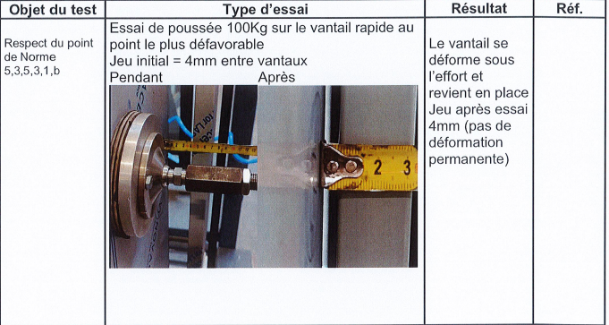
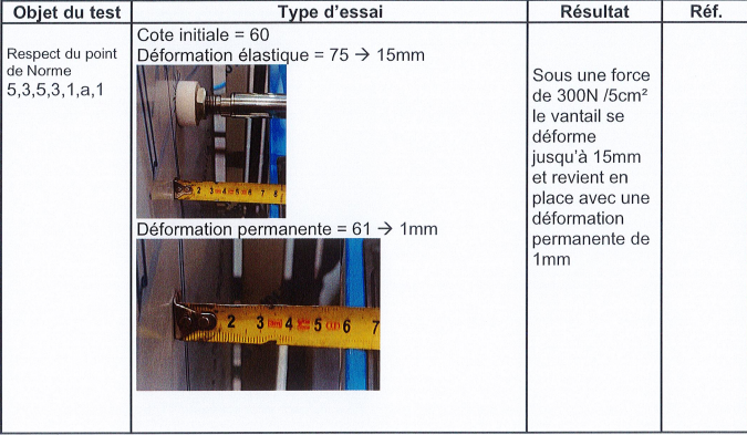
A force of 300 N is applied to the centre of the sheet, which is spread over an area of 5 cm².
The measured elastic deformation is 15 mm, followed by a return to place with a permanent deformation of 1 mm.
2nd attempt:
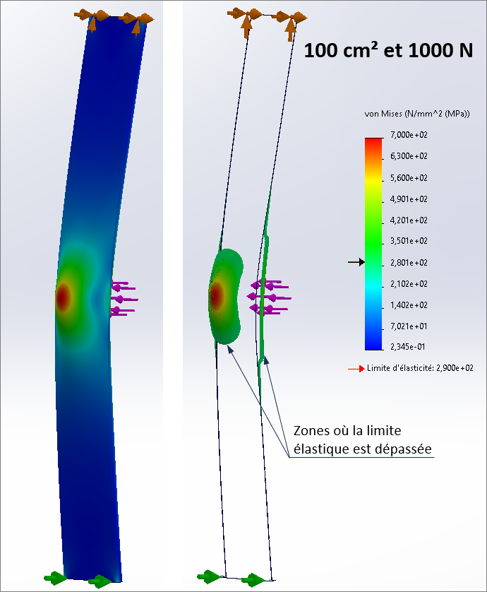
A force of 1000 N is applied to the center of the sheet, distributed over an area of 100 cm².
The elastic deformation is about 35 mm, with a complete return without permanent deformation.
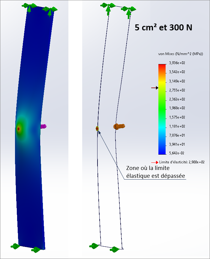
When modeling these tests in SolidWorks, with embeddedness at the ends and a force applied in the center on the contact surface, I expected to get higher stresses in the first test (300 N / 5 cm²) than in the second (1000 N / 100 cm²), due to the load distribution. This corresponds to the actual observations, where test 1 enters the plastic zone of the material, while test 2 remains in the elastic zone.
However, after calibrating my simulation, I see a higher stress for the 2nd try (thus a permanent deformation), which is counterintuitive and not consistent with the real results. And this is true even when both results are below the yield limit, test 2 shows a greater stress.
I'm wondering if I should use a nonlinear static simulation module. Why wouldn't the classical static module be valid, even if it remained below the elastic limit? If anyone has any clues to explain this behavior, I'm all for it.
What shocks my intuition is that, for the same geometry/material of the part, you expect a lower stress with an effort multiplied by more than 3... Even if there is a change in the dimensions of the load zone, this seems surprising from a theoretical point of view, since we seem to be facing a beam (?) embedded at both ends, subjected to a centered " severing " force. Even more surprising if the results of the tests confirm this paradox. Unless it is a thin sheet metal, and the deformation consists of a " punching " of the loading area...
To try to identify the problem, you would need to share your data, part geometry, material, and results of practical tests, especially the position of the permanently deformed area.
The concern comes from the boundary conditions that do not reflect your test. I don't think you welded your sheet metal on an infinitely rigid structure. So you should not put recesses on 2 sides: This greatly stiffens your model because it limits the bending since the 2 ends cannot move.
You have to recess one side. and put constraints to limit the movements of the sheet in the direction perpendicular to the force of the other. Personally, I would only constrain an edge or else you make a local surface to constrain the displacement on this limited surface. If the door is in single support on both sides, the ideal is to do the simulation with the door + 2 support pieces and manage the contacts (much longer calculation with the contact management on the other hand).
Indeed, there is a factor of about 3 between the two forces, but they are applied differently. The force of 300 N is distributed over an area of 5 cm², which corresponds to a pressure of 0.6 MPa, while the 1000 N is distributed over 100 cm², generating a pressure of 0.1 MPa on the sheet. I attach the characteristics I used:
Material: DX51D Steel
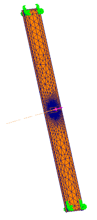
Geometry: The sheet metal is 1.2 mm thick. The other dimensions are: width 23.3 mm, length 290 mm, height 2010 mm. The results of the actual tests can be found below. Since I can only include one file at a time, I will send them to you in multiple submissions. (you will also see how the sheet metal is bent)
Hello Thank you for your answer. I can indeed use the imposed displacements function for this, but if I understand correctly, you block displacements perpendicular to the force, but what about displacements in the direction of force?
Excuse me for the misunderstanding. I meant to block the movements in the direction parallel to the effort and not in the perpendicular direction (or there you have to give freedom to the sheet metal to move). Test photos do not show how your sheet metal is held. This is what will determine the conditions to apply at the top and bottom. Chances are that it will just be simple supports (possibly with a clamp to prevent the sheet metal from moving laterally).
Ok thank you that's what it seemed to me, so I modeled that. On the other hand, my results still indicate a higher stress for test number 2, while this is not the case in the real tests...
I agree with @froussel for the modelling by simple supports at the level of the two edges at the ends of the leaf, probably guided in a groove (and by rollers?). More realistic contacts than recesses. To model, it is sufficient to select the edges and constrain them with zero displacements, in all three directions for one of them, and perpendicular to the surface for the second.
The change in the type of support does not change my intuition: multiplying the effort at 3.3 will cause a deformation and a greater stress with 1000 N than with 300 N. The fact that the bearing surface increases from 5 to 100 cm² (diameter of the support of 25 mm or 113 mm) does not fundamentally change things, simply the factor of increase in stress (or displacement) will be a little less than 3.3.
I have carried out a simulation of the leaf with the section of your diagram and its thickness, without any reinforcement. Conclusion: in both cases the elastic limit (290 MPa?) is exceeded, by 45% in the first case, very locally, and by 155% in the second (1000N), in a more extensive way. This means that there are permanent deformations in both cases. A linear static simulation does not allow us to know the values...
Finally, a question: it is legitimate to doubt the simulation if the results are very different from the reality measured. But the conditions of the real test can also be called into question: accuracy of the measurement (assess the mm with a tape measure!), at what point of the leaf, what reference for the origin of the measurement (a neighboring leaf?), possible displacements at the level of the supports...
@m.blt Okay, thank you for these clarifications but I can't quite understand why the support surface does not play a major role in the stress obtained. Although the force is multiplied by 3.3, the bearing surface it is multiplied by 20. And it is this that tends to reduce the constraint of the second attempt. σ=F/S so for the 300N/5 cm² test, we are at 60N/cm² and for the 1000N/100cm² test at 10N/cm², which for me changes things considerably. The local stress will be much more concentrated for the test at 300N. If I summarize; For me, the increase in surface area mitigates the increase in strength much more.
PS: I confirm that it will be necessary in the future to do better than a ribbon for real tests if we really want to compare!
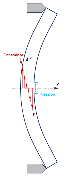
Hello Be careful not to confuse the external pressure with the internal stress of the part, which is essentially the result of its bending around the two directions of its surface (x and z).
On the beam shown below, the pressure is lower with 1000 N over 100 cm² than with 300 over 5 cm², but the resulting force is 3.3 times greater, the moment also bending, and the maximum stress following x as well. The problem is a little more complex in the case of the leaf since it is a shell (2D) and not a beam, but the principle remains...
I would like to add that the rolling direction of the plate as well as of the plates from a different casting are factors that can change the results in real tests. I have already made the real/static comparison on stainless steel tanks, the results were consistent but the displacement was often more pronounced in digital than in real life, with neglected factors such as ZAT, lamination, bend radius etc...