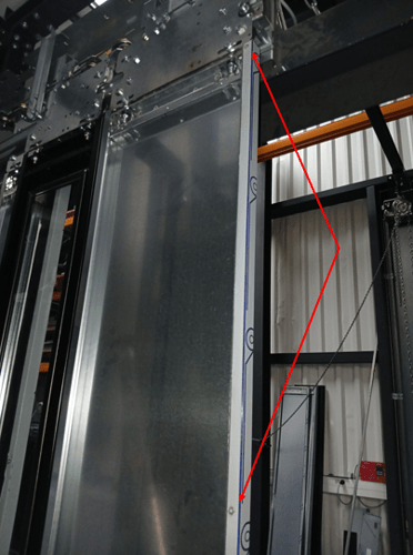
Hello
I am carrying out thrust test simulations on sashes on SolidWorks but I am encountering a problem: Here, it is an assembly of two parts, a 1.2mm sheet in dx51d (the sash) + 1 stainless steel cladding sheet, the cladding sheet is attached to my sash. As here it is therefore an assembly, you have to manage the interactions and this is where I get stuck, I don't see how to define the contact and the function so that it fits with reality. Could someone help me? Thank you


Hello
You need to have Solidworks simulation pro or premium at least and manage the contacts between the different parts.
Logically it's not just contact, there must also be either bolts or welds to connect the parts: to be represented if you want a realistic simulation.
On the other hand, given the surfaces in contact, the calculation may be very long if it wants to end one day. I'm not used to it, but a surface mesh model would surely be more efficient (but more touchy to model in terms of managing interactions between parts).
Hello
Indeed, as said above, you need the simulation module to manage the interactions
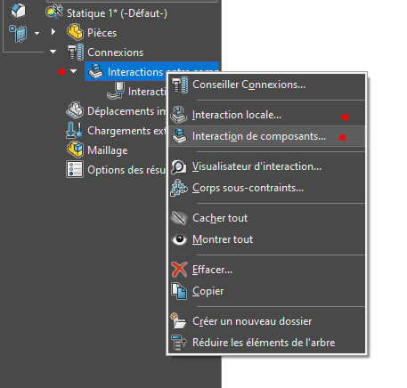
Which version do you have (solidworks and simulations)?
Hello @Scofield, I have solidworks Standard and I have the simulation module (only in linear statics). I was asking the question because in: connections → Interactions between components (as in your image) I have the possibility to manage even without the premium or pro
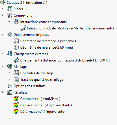
Have you tried to put an interaction between components?
Yes, global interaction and I admit that I left the default settings because otherwise endless calculation.
Hello
you can also save the ASM as PRT, and possibly combine the 2 bodies.
Yes, I just tried and I get something pretty consistent. Thank you
Good evening
An important aspect of the behaviour concerns the mode of connection between the " structure " sheet (1.2 mm thick) and the " cladding " sheet (0.8 mm thick?).
If the connection extends over the entire surface (by gluing), or if it is localized areas (rivets, spot welding), the contribution of the " cladding " sheet to the strength of the assembly will not be the same.
In the first case, the sheets remain bound by the adhesive joint at all points of contact.
In the second case, there will be slippage in certain areas, or even contact breaks.
As for combining the two bodies, this amounts to considering a single sheet whose thickness is the sum of the thicknesses of the two sheets " structure " and " cladding ".
Hence the question: in real life, how is the connection between the sheets made?
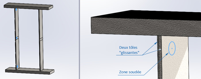

In the images above, unrelated to the leaf, two identical uprights, subjected to the same stress, each made up of two sheet metal " blades " (2.5 and 1.0 mm thick): on the left, the two sheets are " sliding " and welded at two top and bottom points, on the right, they are integral (perfect gluing).
The maximum displacements are respectively 2.7 mm and 2.1 mm, a difference of about 25%...
Hello @m.blt
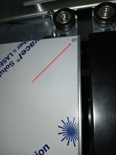
Indeed, the trim sheet is fixed on the leaf with pop rivets (moreover the sheet metal does not completely cover the leaf, it is asymmetrical: fixed with 4 pops on the back fold, well distributed on the height and with two pops on the front, top and bottom): see photo below
On your modelling, I have several questions:
- How are the interactions between components for your two uprights and the blades managed on SolidWorks?
- On the planks, you have sketched in blue the welded areas between your sheets. So you have created a fixed area between the two rooms on this area?
Here I understand that for my cladding sheet, we will be + in your case where the sheets are glued perfectly.
That's it: you have to cut the surfaces to then say that some local areas are fixed together while the others are just in contact without penetration.
Given the length/thickness ratios of the parts as well as the amount of surface in contact it is the kind of calculations that simulation does not like too much (calculations for hours to have a failure in the end).
→ You have to try to simplify the model as much as possible (using symmetry allows you to have a model 2x lighter: it can help a lot because I have the impression that the door is symmetrical and supported at the top and bottom. if the load is not in the center of the door it doesn't work though)
Hello @Tanguy_Ramet ,
A template proposal is attached (SW 2022), as well as a Word doc for comments.
I agree 110% with @froussel's remarks...
The cumbersome nature of the model reduces the computation time, and even its completion as soon as the mesh becomes thinner. Regardless of the solver used. The fault is probably the management of contacts.
There is indeed one symmetry of the model (and only one) in relation to the horizontal plane passing halfway up the door. But not following a vertical plane for the cladding sheet, hence the warping of the leaf...
In addition to complicating the definition of supports, the use of symmetry does not bring any significant gain, neither on simulation time nor on the convergence of the calculation.
Maybe it should be tested more thoroughly than I did...
The simplification of the model also involves the removal of all the small details of shape (holes, notches, etc.) that can be thought to have no significant effect on behavior.
LiftLeaf - SVG.SLDPRT (679.9 KB)
VantailAscenseur.docx (535.9 KB)

