I am currently modeling a room (bedroom) for development work.
Rather than basically modeling solid walls, I draw the BA13 plates as well as the rails for their frame. First of all, to identify their location and for the illustration views to be more flexible (show, hide, move each element). Another interest could be to simulate the forces in case I need to attach myself to it through the plasterboard.
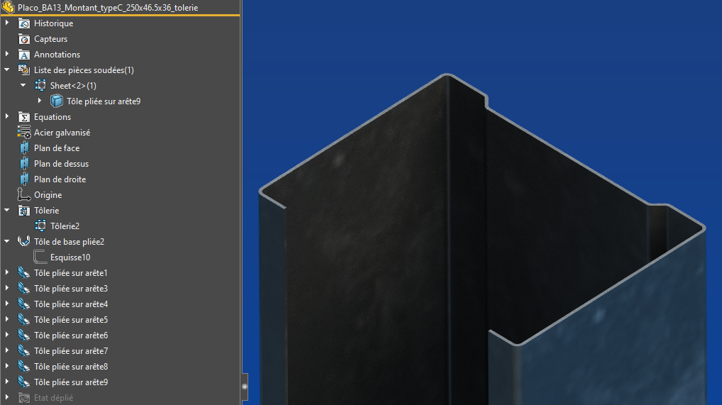
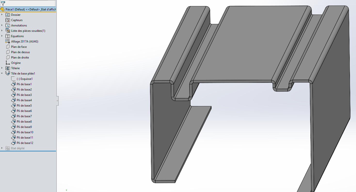
So I modeled the sheet metal rail, but there are a few folds, which I imagine makes the document heavier. I think it would definitely be lighter to just extrude the profile sketch, especially in an assembly where there will be a lot of them.
Maybe not the best design method...
The question is how to ensure a light assembly with a (very) large number of sheet metal parts, while keeping the advantages of their sheet metal status, if there are any?
Is the sheet metal worker status only useful for manufacturing or does it also affect simulations or something else?
In essence, for representation and simulation, can I limit myself to the solid of an extruded sketch or " sheet metal is better "?
For the simulation part, unless I'm mistaken, it only takes into account the material information and not the method of production (for a sheet metal, the important thing is the direction of rolling that orients the fibers of the material and consequently the bending behavior can be impacted as for the bending phases). I would therefore tend to say that it does not matter if we use sheet metal module or solid because the geometry analyzed will be perfectly identical (thickness of material, shape of the plies).
Regarding the performance in an asm, normally it's the number of polygons to be displayed that brings the stations to their knees (for example if there are a lot of sphere-type elements or as we had motor driver windings that were modeled it eats up a lot of resources for not much). On the other hand, the number of bends can slow down the reconstruction, but you can just as easily have only one function to generate this profile, even in sheet metal work (draw the outline and then create a sheet metal function, everything will be encapsulated in a single function).
Another way perhaps to simplify the model is to use the functions of welded construction by considering the rails and mounting as profiles.
I've never tested the performance differences at this level but normally everything will depend on the number of elements to be rebuilt according to the changes. But quite honestly, on a model of a part with uprights, rails and plasterboard, I don't think it's that heavy, regardless of the way you model the different elements. I think it's safe to say that the geometry being rather simple, it won't require huge resources (even if I think SW is not the most suitable for this kind of modeling). The heaviest part of this global modeling would only be if we had fun integrating all the screws for fixing the plates and the framework, there it can largely penalize the opening/reconstruction times.
Edit: I just thought of something else, maybe also use the locking bar at the rails and uprights, so the reconstructions of these models won't be done, it should improve the performance.
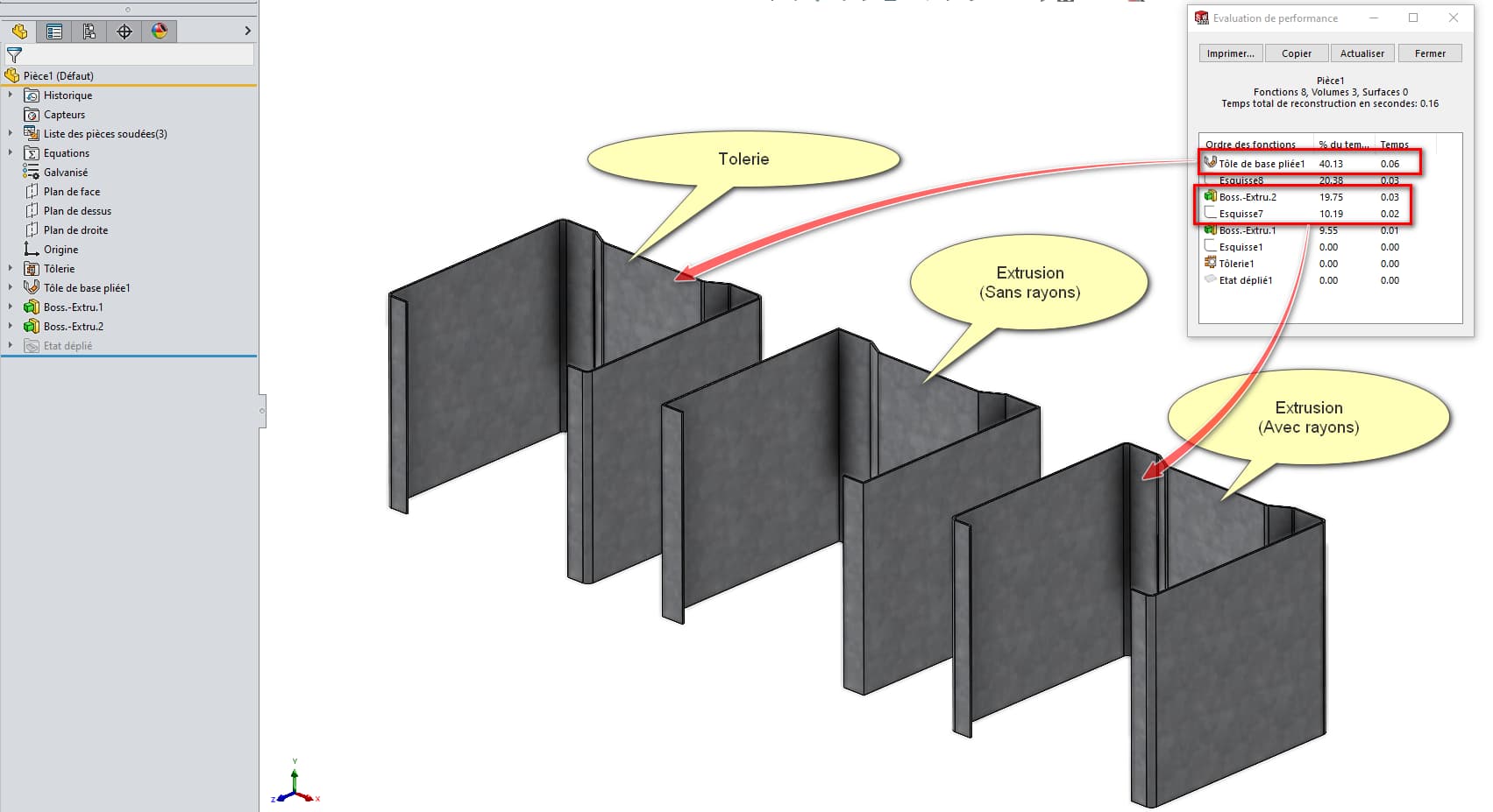
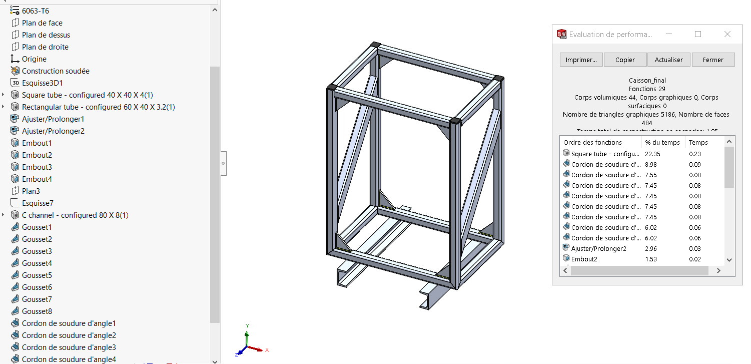
A short comparative test to get an idea (Performance evaluation):
In terms of performance, sheet metal work is the least interesting (40.13% of the 0.16 seconds needed for reconstruction), followed by extrusion with sketch fillets (Boss.-Extru.2) (19.75%), then by simplified extrusion without fillets (Boss.-Extru.1) (9.55%).
I haven't tested the mechanically welded mode, but apart from the fact that I have to create a sketch (*. SLDLFP ... which is not very complicated), I think it remains the best compromise between " lightness " and " Simulation "... in the sense that a single sketch allows to " link " several profiles together (a sketch = an entire wall section) but also the simulation of load(s) can be carried out on a part (the group of mechanically welded extrusions) ... It will be easier than running a simulation on an assembly.
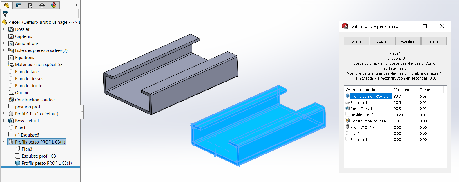
Hello For my part, I think that mechanically welded is, as @Maclane indicated, the best compromise. I did a small perf test, on a mechanically welded solid created from a profile that I added to the list of weld profiles The mechanically welded solid takes up more resources than the same " extruded version" solid
but in the context of a set of profiles, it seems to me that there is an obvious gain in terms of reconstruction time