I will have a question I just tested Solidworks 2022 online to see the CAM version, I did some testing, but my question: Do you think that Solidworks CAM can perform on kind of profile, and output it for a sharpening machine
Because the test I was able to do only lasted 2 hours and honestly it is currently inconclusive, because I have not been able to test all of them
I don't see what would prevent milling this type of profile.
On the other hand, once your sketch is done, you have to do it in two passes, one which makes the rounded parts first, then the right part by removing rays.
Suppose that your workpiece is fixed on the z and X plane, the head being in the Y axis, you make the whole profile by rolling on the side of the cutter. Then after rotating the head in a Z you remove the rays that will still be present when two straight lines meet.
On the other hand, I don't know what the size of your profile is because you have a delicate point at the bottom of the profile (at the bottom of the big slope) you will have a problem with tool length with bending if your cutter has a long length. Personally I would make a laser sketch if the profile is not too thick (less than 14 mm thick). A single tool with head or workpiece rotation is not complicated even for SW CAM
We actually have a system with a grinding wheel that comes in from the top and according to what I know, they make a finishing pass because he already drafts in manual
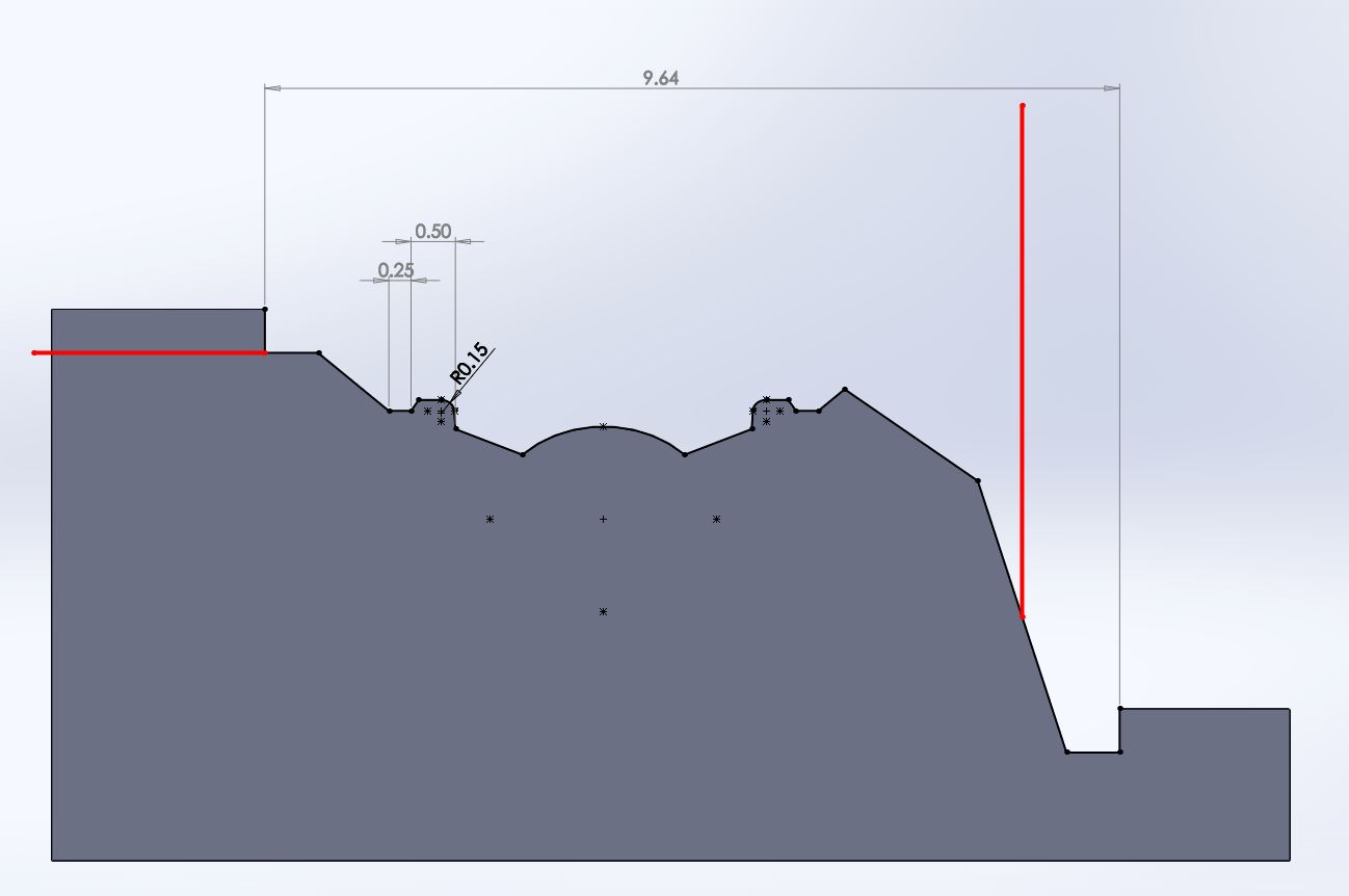
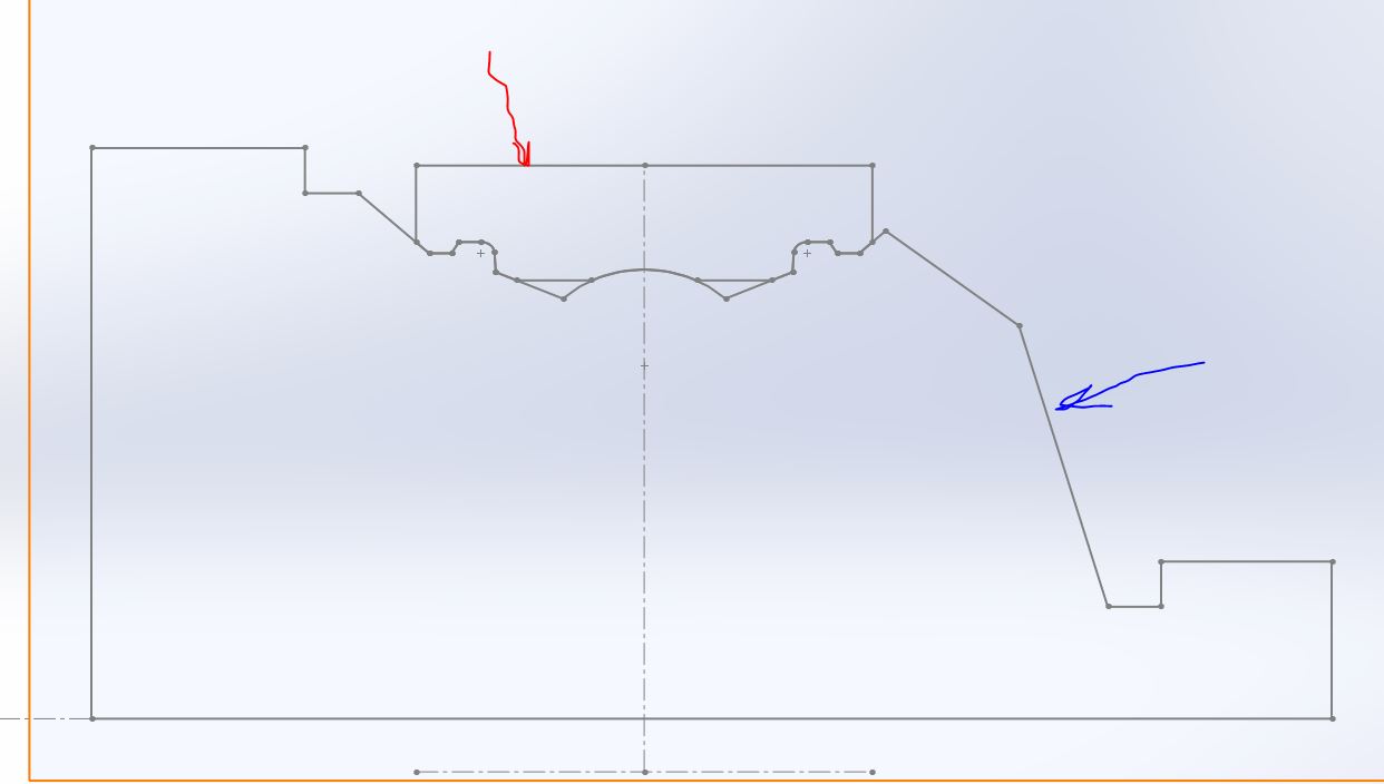
The red part represents the exterminity of the tool, so we clear a little to the right for the pre-cut
I put the most sensitive sides for you, because that's where the bearing protections are mounted, for the ends we leave 0.6mm, and a small thickness at the end to allow to finalize the part
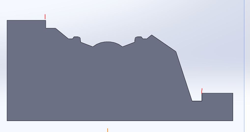
I don't think I understood. What I understood 1°) it is a profile that will be fixed on a sharpening machine and will serve as a guide. The goal is to make the said profile.
To make the profile you use a classic milling machine or CNC since you use SW CAM.
The part is fixed on a support and the program make the shape of the profile indicated in black above
Currently we use a Mecanic program to do the NC programming, so we create what you see above and then we transfer to the program in dxf format, then from Mecanic we transfer back to dxf to go back to solidworks to print the plot that we put on the small gray screen
And we would like to remove the Mechanical interface, with an interface included in solidworks, so SW Cam that we don't have yet
But before it I have to confirm to my superiors, that we can do this on SW cam, and I am willing to send you the file tested above to confirm me
The black profile as a complement, it is the chisel that will be used to manufacture the parts
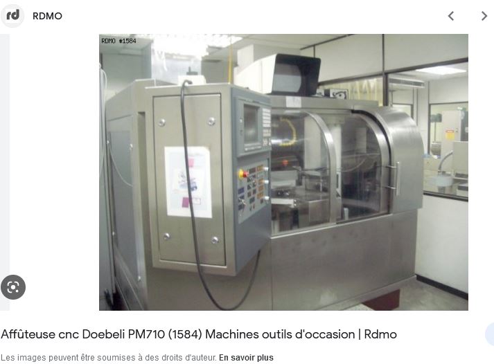
For me I don't see any problem except for the file names and format between the two machines. You can ask the VISIATIV sales representative to give you a demo on this specific case (even simplified). And to see how you integrate the output file from SW CAM to Doebli because if they are an esoteric interface it is better to check.
Kind regards
PS: I no longer have CAM because I delegate to my subcontractors.
@Zozo_mp I was able to get in touch with our dealer He will look so that we can do tests in our company for a while to see if its working on our machine I am waiting for this news, I'll probably ask you questions if I have any doubts Because officially I only used 2 hours solidworks cam I'll leave open the time for the tests it will prevent me from opening a 2nd subject
I had used SW CAM to generate paths that I converted to grbl for a humble 3018 pro. Its use is not easy and often requires a few feints (at least in my use). I don't remember too much but there are certainly answers that I can provide. For a real professional CNC, already more SW target, compatibility is undoubtedly better and easier to use and configure.
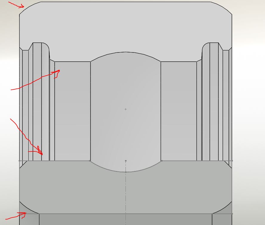
@Sylk On the profile, the red lines represent the cutting tool We make the shape of the cutting tool, on an external or internal jacking chisel To machine the part that will become an outer or inner ring in the bearing After sharpening, the profile will be used by internal or external jacking to machine the shape of the rings indicated by the red arrows
Hello everyone, I'm reopening the question, I'm doing Solidcam tests, but I find myself in a bind, to do the manipulations, Choice of tool, position of the Zero points and make the profile in 2 parts Help, if someone can give me some explanation please thank you in advance