Hello Zozo,
I also have my license for the 2022 on my desktop, not on my laptop because I can no longer make changes to a 2021 and transmit it to people who don't have the latest version in their office to be able to modify parts (in 2021), it's complicated ...
To validate your method and apply your advice, I will go back to the study of my crank pin and do the two versions in the morning, plus the analysis of the forces with the m.blt sheet.
I am learning new things and especially how this simulation tool has been structured by your remarks and advice from both of you, thank you.
Hello
Thank you for explaining the configuration, it's instructive and formative.
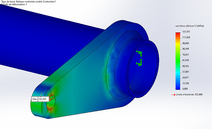
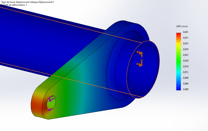
Concerning the torsor (sweats listening to this word... with the risk of errors in the long run.) I will be able to change the center of reduction and place myself at the critical point, I was very interested at the first sight of the cord tracing and to note a variation of the apothem in relation to the loads and reactions this allows me to get an idea of the resumption of forces and then maybe consider a discontinuous cord, but this intuition would weaken the welded assembly I think.
Kind regards.
Spectrum.
Hello
I am very happy with the approach to follow with the play between my two pieces.
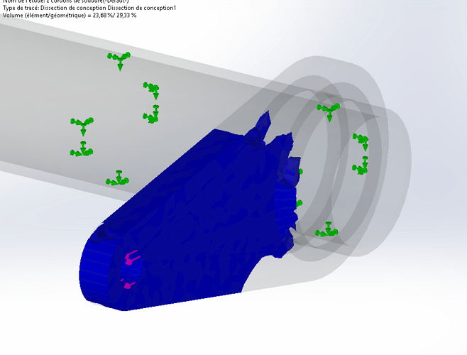
Thanks for the design dissection tip, I don't know... Not good.
I will be able to continue my simulations.
Have a good day to you.
Spectrum.
The solder doesn't move, I have the apothem of 1/4 inch, 6.35 mm.
and dissection.
Hello @spectrum
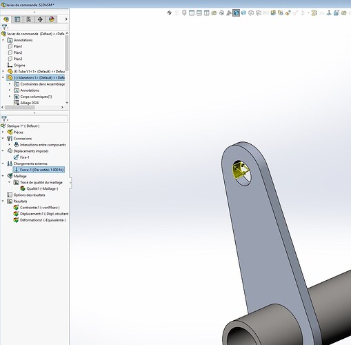
AMHA, personally I wouldn't have put the effort in this place on the crankpen.
If I refer to the beginning of the post and also to the common use of this type of assembly: the crank pin makes the tube work in torsion.
So not as you put your efforts.
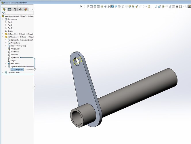
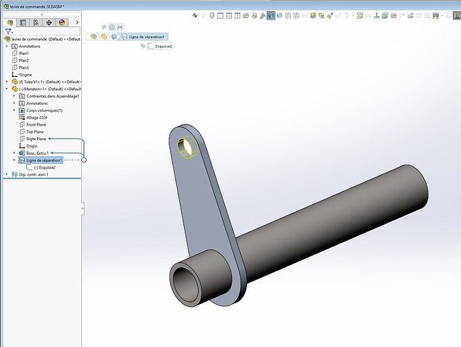
A sketch must be made in the hole and completed with a dividing line inside the hole.
I have the 2022 V-file if you want
Kind regards
Hello Zozo_mp,
Ah I hesitated to put a separation line on my bore (like a bearing load that touches 1/2 surface with the presence of the play with the shaft) because originally I had put a separation line inside my tube but by putting a shell, I had an infinite displacement ... no connection between the two 1/2 hulls well that's my personal understanding ...
I am willing to look at your parameters to confirm the implementation in volume and I will stay in volume, not easy to use the solder connector because it requires a concurrent edge and with the play not possible it is necessary to make a configuration derived by a variable set =0.
Ok for my mistake on the search for twisting, carelessness ...
Thank you for the information and advice.
Hello
Here is the V-zipped file 2022
For the solder connector I think you don't need any play.
I don't have too much time to look but normally connector means that it connects two elements together
This means rechecking that your two pieces (without play) must be declared " free " in the interaction between components at the outset.
Be careful, a separation line allows a calculation with an approximate value because the purpose is only to measure the torsion and possible deformations of the crankpen.
This is not comparable with a " bearing load", not least because the bearings are fixed and they do not measure the same thing at all.
Kind regards
.zip control lever (239.6 KB)
Hello Zozo_mp,
From my attempts, if a play is present between two elements, by the geometry the connector does not find a concurrent edge so this path is impossible from my beginner experience.
What bothers me is the obligation to be orthogonal between the two surfaces, for example an element oriented at another angled angle and the connector becomes refractory!
OK, it's noted and archived to have adapted tools. Thank you.
Kind regards.
Spectrum.
Your miseries on soldering is in line with my own difficulties with SW soldering.
So much so that I sometimes wonder if designers have ever set foot in a workshop that does welding. We could send them on an internship with @OBI_WAN !
It's been ten years since I gave up welding in sub-ASM and ASM, it's unmanageable and too talkative. I put the indications directly in the MEP, which is more than enough for welders who are not Mickeys and who understand very well the intentions of the assembly.
My colleagues may be more nuanced on the weld.
Kind regards
yes @Zozo_mp
Welders are pros and their experience is a richness.
Personally I let them do it because welding is their job, not mine, on the other hand, like you, I put impositions because I have the overview of my assembly, not had.
may the force be with you.
