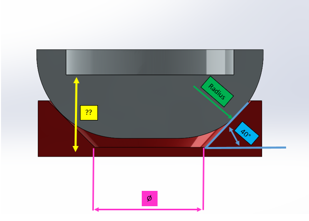
The purpose of my calculation on Tolanalyst will be to determine the yellow height (from the bottom of the red part to the counterbore of the gray part). This dimension depends on several measurements, including the ones I indicated in the image (the radius, the angle and the diameter on the red part). Will it be possible to perform this maximum and minimum height calculation based on the other dimensional tolerances associated with it (radius, angle and Ø)? From my research, it seems that Tolanalyst has a hard time taking radii and angles into account. Thank you for your help.
Hello @m.blt , Thank you for your idea, which is very interesting, but it does not fit my process for several reasons. Firstly, large dimensions are subject to tolerances. My objective is therefore to determine the yellow height at its maximum and minimum according to these important dimensions when these are at their maximum or minimum values. Second, this is a two-piece assembly, and I have about a hundred similar assemblies with minor differences in dimensions. Thus, following this approach would require recreating a new sketch for each assembly grouping the two parts together only for this calculation. Indeed, my diagram is missing dimensions but I had made this assembly just to represent a case similar to my case / request. Concerning the Excel spreadsheet, I also thought about it, but it does not meet my specifications which require that it be done on SolidWorks...
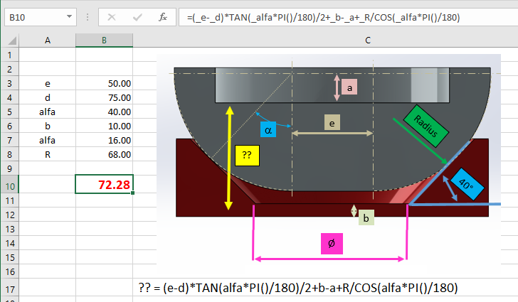
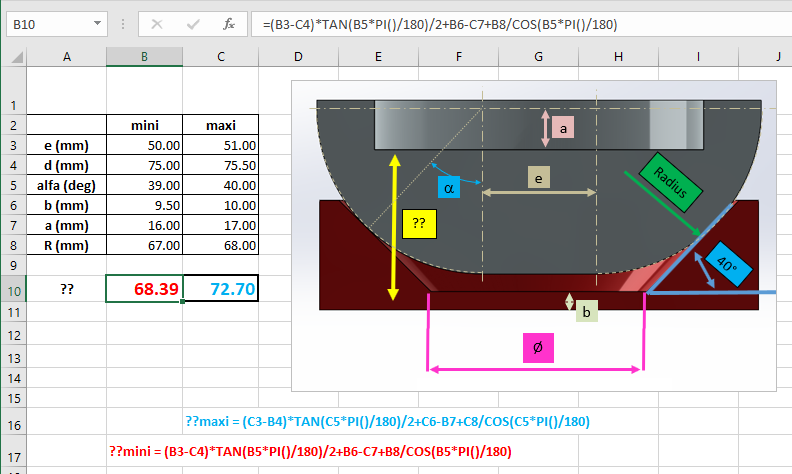
Compared to the number of situations envisaged, the numerical solution associated with Excel is undoubtedly more suitable than the SolidWorks sketch. As for tolerances, it would be sufficient to consider two cases, the first giving the maximum dimension, the second the minimum dimension.
If Excel is not suitable, there is still the possibility of doing the calculation in the assembly by a macro. Provided that each assembly uses the same notations...
Yes, each blend follows the same principle, but with variations only in values. A macro-based solution could therefore be possible to automate this process. However, I am concerned that TolAnalyst will not be able to perform this type of calculation involving radii and angles. I have contacted my reseller and am currently waiting for a response from technical support.
Could you enlighten me more about your idea about macros? Thank you for your cooperation.
By macro, it is possible to retrieve the values of the dimensions of the parts of an assembly and their tolerances, then to apply the formula giving the resulting dimension, in minimum and maximum values.
The ideal situation : to apply the principle systematically, you would have to have the two parts have the same name in each of your assemblies, and the sketches and dimensions should also have the same name in the parts of each assembly...
Failing that : if this is not the case, we can imagine opening each assembly, selecting the 6 " parameter" dimensions in order, and applying the formula for calculating the minimum/maximum dimension.
It's a solution that could interest me. In my case, the names are not the same, but I see that your solution would still work. So, if I understand correctly, in my case, I would have to open the assembly, manually select the "6 parameter dimensions" and insert them into a macro in which I would have previously created a mini/maximum dimension calculation formula. This is still feasible despite the fact that I want the maximum and minimum calculation? This means that when I select the "6 parameter dimensions", how will the software know how to take the dimensions at the maximum / minimum and not take their nominal value? To put it more simply, the question is will the software be able to differentiate between the minimum and the maximum when I select in Solidworks? Is everything possible on Solidworks or is a secondary platform necessary?
Hello In my opinion, the only problem with the macro is how to indicate the direction of the links in the dimension chain (which is what auto tolanalyst can do) to know which value to take (min or max of the dimension depending on the desired result) Apart from always selecting in the same order or adding checkboxes to give the meaning, I don't see a "simple " solution.
No, I haven't tried it yet, because it's my first time using a macro in CAD. I start by studying the features of macros to determine if my goal is achievable. In your opinion, the only problem I could encounter would be to define the dimensions in maxi/mini, for example, when I look for the maximum height, all the dimensions going in the same direction as the height would be in maxi, and those going in the opposite direction would be in mini?
The problem I have with TolAnalyst is the complexity of the assembly. It seems that TolAnalyst is having difficulty handling complex shapes. In my case, there are radii and angles dependent... (See image attached to my first message) and at the moment I have not been able to perform a correct calculation on this type of assembly with the help of TolAnalyst. If the calculation is feasible on TolAnalyst it will be perfect.
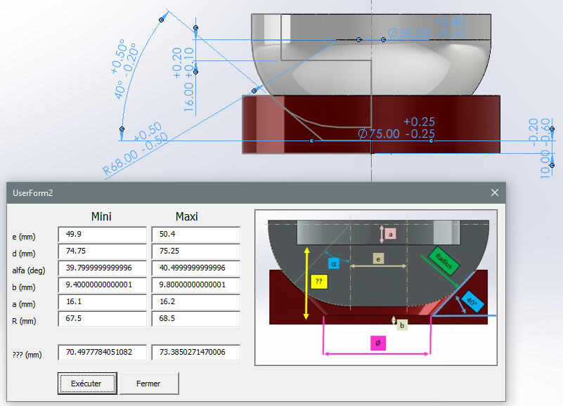
Attached, a macro sketch on an assembly sketch... The dimensions (and their "bilateral" tolerances ) are selected by their names. The minimum and maximum values are displayed in the TextBoxes of the UserForm2 form. The [Run] button calculates the minimum and maximum of the dimension to be evaluated.
It is clear that the calculation only makes sense if the geometry conforms to your illustration, and the same for all assemblies, . Otherwise, I agree with @Cyril.f.' s remark about the direction of the dimensions. SolidWorks does not define them, so it must be assumed that the orientations will be the same for all assemblies.
The weakness of the method is the selection of parameter dimensions, based on their names. The macro can only work on the joined assembly. When names change over the course of assemblies, the macro must be adapted accordingly. Galley! The solution would be to provide for an interactive entry of the odds, but this is a more complex matter...
I have one last quick question about your programming, have you programmed everything by hand or is there a slightly simpler way to do it? Thank you very much for your collaboration, I will try to work on my side to achieve the final goal...
Totally artisanal work... SW's API help is inspiring with its multitude of examples. Another source of quality inspiration: https://www.codestack.net/solidworks-api/.
And if VBA is the most accessible and widespread language, others are more efficient... Good luck.