hp08
July 29, 2021, 5:25am
1
I would like to report a bug for the TOLERIE function.
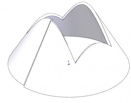
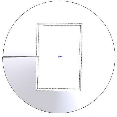
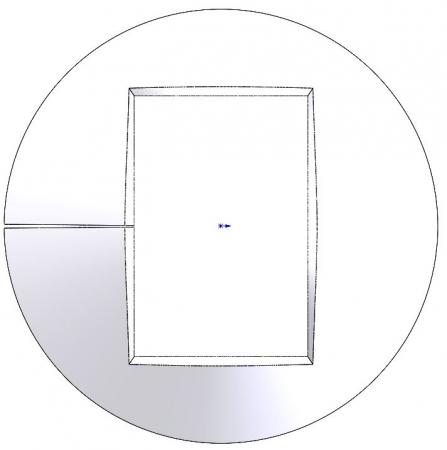
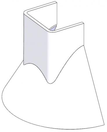
A systematic shift appears on a CONE-PRISM intersection.
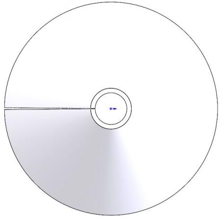
The cone is defined simply with a straight line.
Any thickness is applied as well as a partial revolution at 359° for example.
Function 1 is not a problem
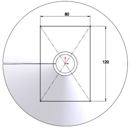
The removal of material from material is defined by means of a sketch in the top view.
The odds are not important...
The result is correct and in line with expectations
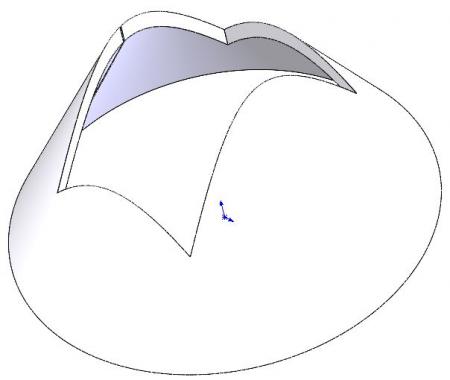
The problem appears when using the sheet metal function
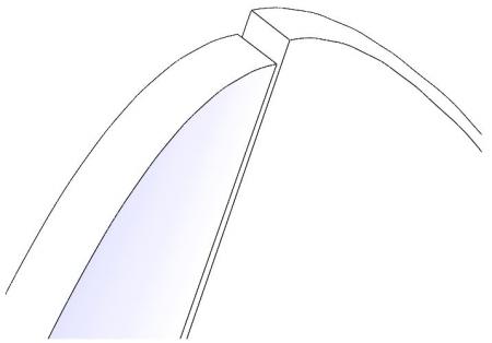
The thickness appears correctly, however an abnormal offset systematically appears.
There is a bug.
What is the solution ?
Do you have a lead?
Thank you
part2.sldprt
Hello
You are on the designer's self-help forum and not on a Visiatv after-sales platform to report the dugs.
2 Likes
To fix the bug, simply move your material removal after folding and check the box Normal material removal and the bug disappears. see PJ
ac_codra_427.sldprt
3 Likes
hp08
July 29, 2021, 6:44am
4
Thank you for your quick response.
The solution gives me a lead that is not totally satisfactory but I will test.
It is the relative position of the thickness that poses a concern for the docking to be perfect with the tube.
I test and thank you again for your solution.
The position of the thickness reflects reality because your cone will be laser or plasma cut and the normal material removal allows for a perpendicular cut to the thickness as for cutting. If you don't want to have that, you'll have to go through a machining operation.
ac_codra_427_-_1.sldprt
3 Likes
Hello
As ac cobra 427 specifies very well that I salute in passing, the laser cut will be perpendicular to the "unfolded" part.
2 Likes
hp08
August 3, 2021, 5:03am
7
After testing several solutions, I give you my conclusions.
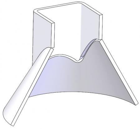
First, I wanted to have a natural chamfer docking between a cone and a rectangular tube.
The solution chosen gives us parts that conform to the above clichés, but the parts are not developable.
To obtain these coins, you have to work around the software's problems and bugs.
We have a beautiful image but this one is useless.
As mentioned in my first message, SolidWorks is stuck on this type of part.
I am attaching my assembly file.
Thank you for offering me solutions.
cone-tube_rect_v3.zip
gt22
August 3, 2021, 12:12pm
8
Hello @hp08
Post your parasolid parts and assembly
I think that you should not make a cut before but after the installation of the tube
Create your tube via extrusion to the surface of the cone via an offset sketch
and only then pierce the cone
Take each piece individually
cut them and transform them into sheet metal work
and unfold them
@+
1 Like
Hello hp08,
I don't know the section of your tube, but it seems to me that it is possible to cut inclined cuts via the "laser tube"! As a result, you have two pieces that go together quite well!
Kind regards
hp08
August 3, 2021, 2:39pm
11
Continued with the pieces
piece3.x_t Part2-v4.x_t
Hello
Attached your fold-out parts; They could not unfold because your sheet metal bodies were removed and replaced. For the cone, the sheet metal is replaced by a body of revolution so not unfoldable and for the tube it was the lower part in sheet metal that you replaced by the upper part not converted. see PJ
ac_cobra.rar
2 Likes
