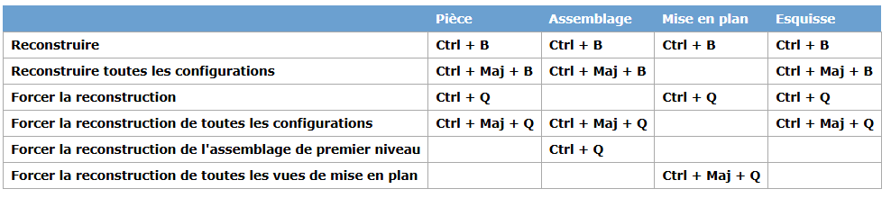
New user of SW for 1 month after 15 years of Creo, I continue my learning... and my struggles. Bear with it if the answer is simple
I created views on a plane and later realized that the default representation of tangent edges was wrong, i.e. in strong line and not thin line. I figured out how to change this in the document properties and saved my 'ISO-modifié_xxx' config.
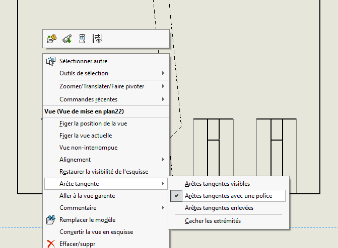
On the views that followed this manipulation, the tangent edges are now correct but nothing happens on the views created before (i.e. >80% of the views on several folios with dimensioning completed). What for?! I have the impression that the old views are frozen, that we can't edit / update them. A bit like with the sections where a classic projection view cannot be converted during the reflection of the shot, hence my question: are the views taken in fact frozen forever and are only a bunch of lines? (it seems so stupid to me that I must be missing something for sure)
I even voluntarily reloaded my modified ISO, I thought that maybe I should force the regeneration a little but nothing.
Solidworks has a very personal methodology when it comes to its management of " models " (in particular the drawing and background plans, but this is also valid for the models of parts, assemblies, etc...) As you may have guessed, Solidworks " saves " the document model used with the 3D component. This is a known issue when updating said templates, it only applies to new documents. But then what to do with the old documents?
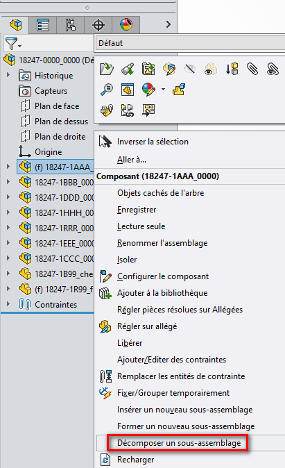
- For assemblies, it's simple:
Create a new empty assembly (using the new templates)
insert the old assembly to be updated
And break it down
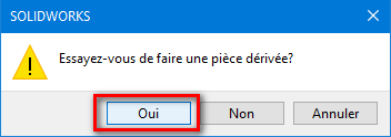
For the parts it's more complicated (but the principle remains more or less the same):
Create a new empty room (using the new templates)
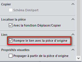
insert the old document to be updated (derivative document)
And break it down, but this time by clicking on "Break the link with the original part.
As for the drawings, it's still different.
Open the drawing you want to update
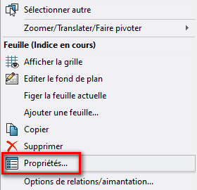
Right-click in an empty area of the sheet and click on " Property " Re- select the MEP format (via browse or Reload) and then apply the changes.
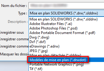
Be careful to remember to save the " Standard used " as well as the " Basemaps " WITH your new drawing templates (*. DRWDOT)
… But most of us use macros to simplify this type of process. Like what:
Thank you Maclane for this extremely complete answer.
For assemblies and parts, I keep your post in memory if needed. For the plan, I just did your manipulation and it doesn't work because I miss something. If I manage to save the .drwdot, I obviously don't do it well for the .slddrt because when I open it and it creates a " bogus " drawing for me, I have everything by default, the lines like the ISO. So I'm going to dig into this intermediate point before I can properly reload the background.
MEP models (drawings) are not always easy to grasp...
The subtlety is that a drwdot can contain a slddrt, so if you save a drwdot that contains a slddrt, creating a drawing no longer requires you to choose a basemap.
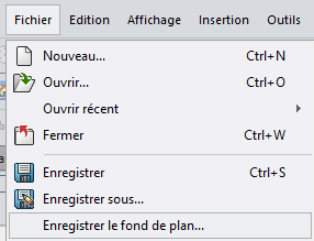
When you save your drawing templates (*.drwdot) = Save As => Drawing template
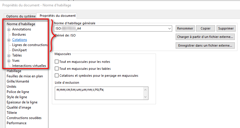
But before saving these two files, you must make sure that the Standard to be used in this drawing is the correct one: _exemple for my A4 sheets:
Be careful, the Standard does not include all the settings of the Document properties... they will have to be configured manually for each different MEP model... I admit that I use this technique so that I don't have to remember which files are contained in such and such information: I save them all with each modification. (Templates + Basemap + Standards)
I checked what I had done with what you explained and I'm good. When I create a new plan, I have the modified standard I made for myself (and the story of the strong/thin lines). Same when I reload the basemap.
But the problem of refreshing views persists. Thanks to your help, I see that what I've been looking for, doing and understanding for a few weeks is good but now I'm drying up and I think I'm going to put it down to the bug, at least my next plans will be clean.
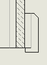
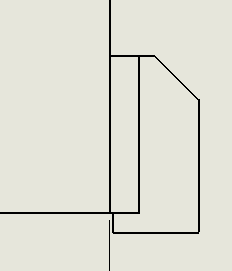
Here is the difference on 2 folios:
Thank you for your time and unless there is another idea to propose, I'll leave it like this. I'm going to reassure myself by thinking that there are much more disgusting plans than my little incoherence