Hello
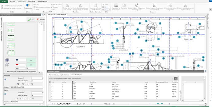
On solidworks inspection I don't understand the logic of the software, if someone can help me it will be great to locate my dimensions in character area.
My grid is well modeled on my plan with the right number of rows and columns as well as the meaning, however in my table manager nothing matches, maybe an update story I don't know...
