I allow myself (again)... since I have (still) not seen anything on this platform or the forum.
At the beginning of the year, 3DEXPERIENCE WORLD (February 23 to 26 for the year 2025) took place in the land of Uncle Sam with the creation of a Top Ten List of improvements desired by users in SolidWorks products.
The link to the 3DSwym community:

It works on the principle of " copy right @Maclane I think".
Once again, I watered quite a bit (non-exhaustive list!):
SPR 769752 - Ability to set certain drawing sheets to be skipped in the total count of sheets and exports
→ Some drawings may contain sheets that are only used for internal reference and should not be provided to customers/manufacturers, etc. However, the presence of this sheet affects the total number of pages and can be confusing if the recipient thinks a sheet is missing. The possibility to exclude a sheet from the total count and optionally exclude it by default from the list of sheets to be exported as pdf would avoid this problem. The current workaround is to break the parametric link for displaying total page numbers, which is not ideal during production.
Flexible components: Use a definition assembly whose data needed for reconstruction is stored in the component's document as a flexible reference folder (similar to Smart Components)
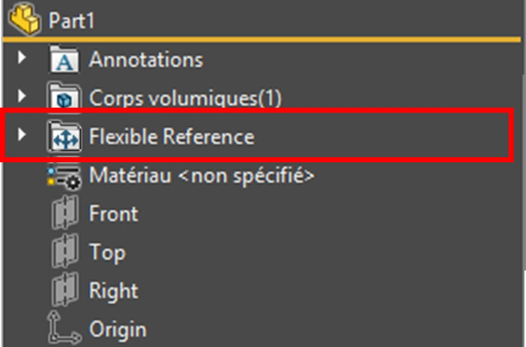
→Currently, flexible components are built as part of an assembly. If this assembly is unfortunately large, when changes are needed, this assembly must be reopened, or a new assembly must be created and external references reassigned. I admit that it's possible to build the component in the simplest assembly possible and then delete it, but in this case, the modification will require a rebuild context, whether it's a temporary assembly or an actual assembly for validation. The idea I submit is to use the same workflow as the one used for the smart component, and create a simple assembly whose data needed for reconstruction is stored in the component's document as a flexible reference folder, and use a similar "Edit in definition assembly" command when changes are needed. In companies where people are dedicated to creating standard components (including flexible components such as springs, bellows, etc.), this could be advantageous.
Smart component as an "inserted part" in a room: "Smart functions" usable/operational
→ I would like to be able to use the smart features of one part when it is inserted into another room, which will save me time and limit either re-entry errors or construction errors. *
Example: a welded construction with sheet metal and nuts to be welded. Currently, I either use a library function that allows me to generate the hole and shape of the nut, but asks me to enter the information in the properties of the element, or I use the "Insert Part" function, which allows me to transfer and retrieve the properties of my nut (description, material, reference, etc.) but asks me to create the hole. If the nut contained any smart features that I could use when inserted into another room, I'd be thrilled.
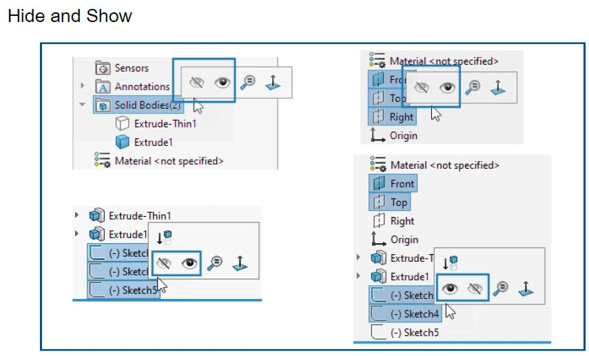
" Coating/Processing " object in the FeatureManager tree
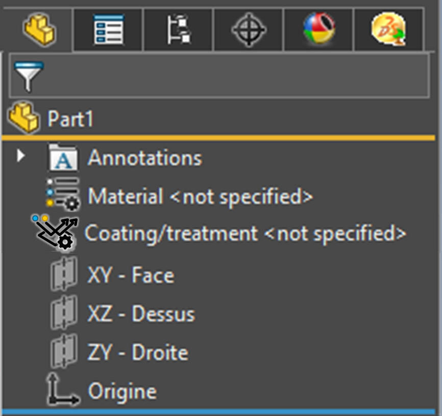
*→ Create a FeatureManager tree object (and associated database) that is similar to a material, but for treatments/coatings that, like appearances, can be applied at the surface, body, or entire part level. When applied at the body level, the same object will appear under the body, as will the material. When applied to a face or a group of faces, provide a tree folder dedicated to named entities (face and edges) so that the same cladding/processing object can appear under a named face. (allowing a group of faces to be named could be advantageous in this case...)
Specific folder for named entities (faces and edges) in the FeatureManager tree
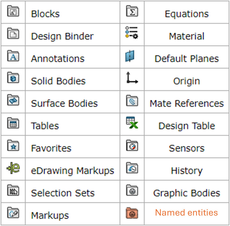
→ Add a new FeatureManager tree folder dedicated to named entities (face and edges) so that users can see at a glance if named entities exist in a room. Currently, the user must right-click on the part name at the top of the FeatureManager design tree to find out if there are any named entities
eDrawings: Option to set the location of the gtol.sym file to use the same as SolidWorks
→ If you customize the gtol.sym symbol definition file, when you open a drawing containing your custom symbols with eDrawings, those symbols will not be displayed, because eDrawings uses its own symbol definition file by default. A registry edit is required to change the location of the gtol.sym file used by eDrawings to use the same gtol.sym file as SolidWorks. The ability to set this location from the eDrawings options would be much appreciated, as it would be much easier than editing the registry!
Part insertion functionality: Ability to apply the part material from the source file to the body of the derived part

→Most of the time, we apply material to the part, not to the body. Therefore, when inserting a part into another part, we currently cannot transfer the material, except at the part level in the derivative part. However, I would like to be able to apply the material of the source file part to the body created in the derived part.
Repeats function: possibility to repeat a function AND a body in the same repeating function
Access the Materials database without having to open SolidWorks and a part document
→ Provide an independent application such as the Toolbox Settings to access the Materials DB for viewing/adding/editing.
Material Database Interface: Ability to link/attach a file (.pdf, .doc, etc.) to a material
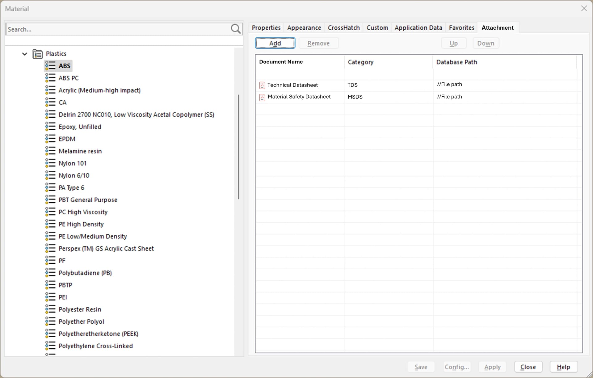
→ Improve the interface of the material database with the ability to list and link documents such as technical and safety data sheets, REACH and other certificates.
I don't want the document to be stored in the part file. What I want, to be precise, is the ability to list the documents associated with a given material in the database, no matter where those documents are saved on a server or in pdm, with the ability to open those documents by double-clicking on the corresponding line.
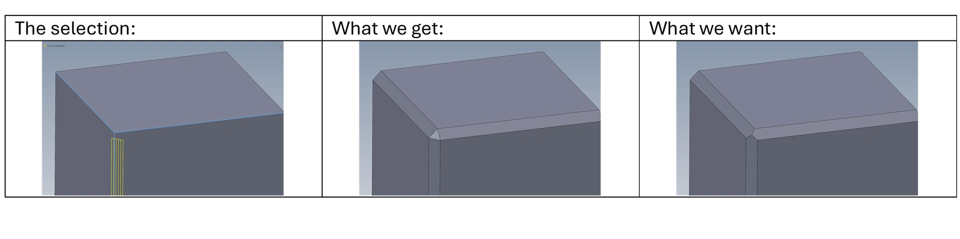
Chamfer option to keep the top
Knurling Performance
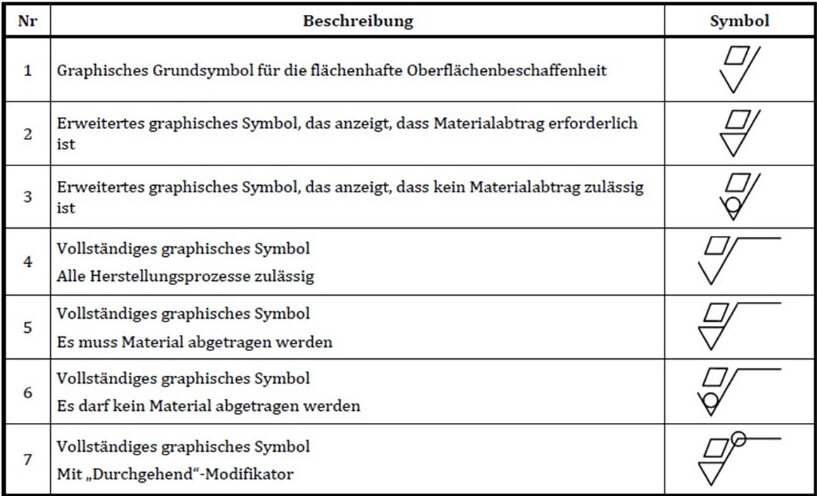
→ Added a function similar to the thread representation to apply a knurling representation to a surface: modification of the appearance and legend in accordance with ISO 13444 recoverable in the drawing.
Left-hand thread
→ Added a checkbox in the Drill Wizard - Tap Hole to mark the tapped hole with thread on the left. In drawings, drilling annotations this translates into the addition of the -LH as the standard requires.
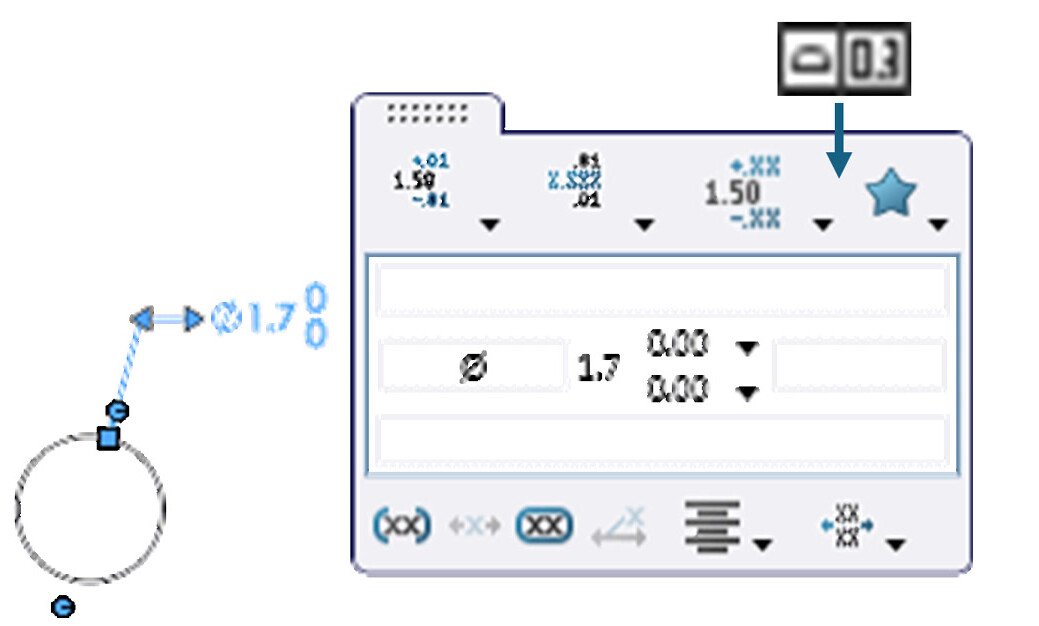
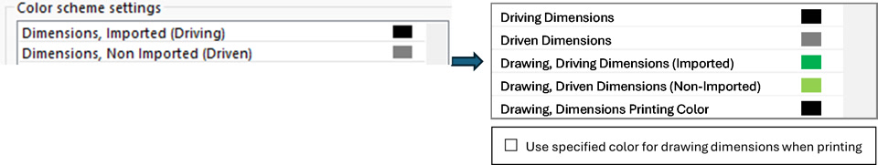
Customizable color coding of model dimensions and drawings independently
FeatureManager inverted tree: last operation at the top.
→ Added a system option to invert the featuremanager tree so that the last element created appears at the top of the tree (i.e. right after the origin). The recovery bar should then be moved upwards and the blocking bar from the bottom. The goal is to keep the latest features close to the basic plans, origin and favorites folder, etc., and save the user from having to continuously scroll down the tree and then up and down.
Color parameter for components excluded from the BOM
→ Envelope components currently have a specific color and transparency status in the color settings of the system options. It would be appreciated to have the same parameters for components excluded from the BOM.
Drawing: Insert the trajectory length dimension with attachment lines delimiting the trajectory when it is not a loop
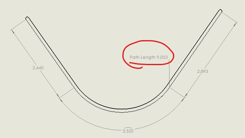
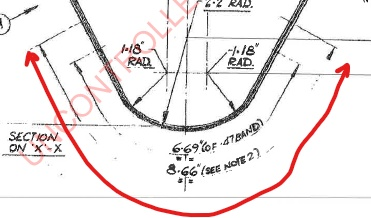
→ The path length adds only one attachment line and one note, which does not define the location of the path endpoints when the path is not a loop.
Mass Property Dialog: Override Density
→ Added the ability to override the density of the material in the Override Mass Properties dialog box. In the case of parts that are designed in context and are simplified to represent, such as a spiral pipe, the mass currently has to be manually rewritten every time a design change is made that impacts the geometry and length of the pipe. The ability to replace the density would allow the mass to be automatically recalculated and avoid the need to create a specific material that is really not ideal as a solution.
Vector image import (.svg, .eps, etc.)
→ Directly import .svg, .eps, and other vector image files as sketches. Often, engineers need to include their company logo or other image in parts files. However, this can be difficult if you only have vector images of your logo. Currently, SOLIDWORKS is not able to directly import .svg, .eps, and other image files as sketches or use them as sketch images or decals. The current solution is to use third-party vector editing software to convert the vector image into a .dxf file, which SOLIDWORKS can import as sketch entities.