Bonjour,
Sous Solidworks Premium, je souhaite simuler les déformations d’une pièce sous contrainte (zip joint). test_0.zip (232,3 Ko)
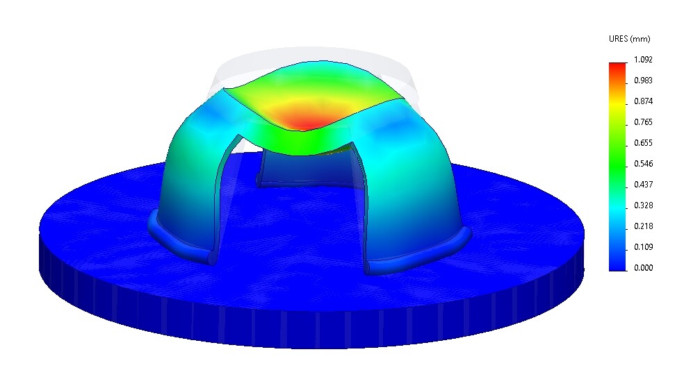
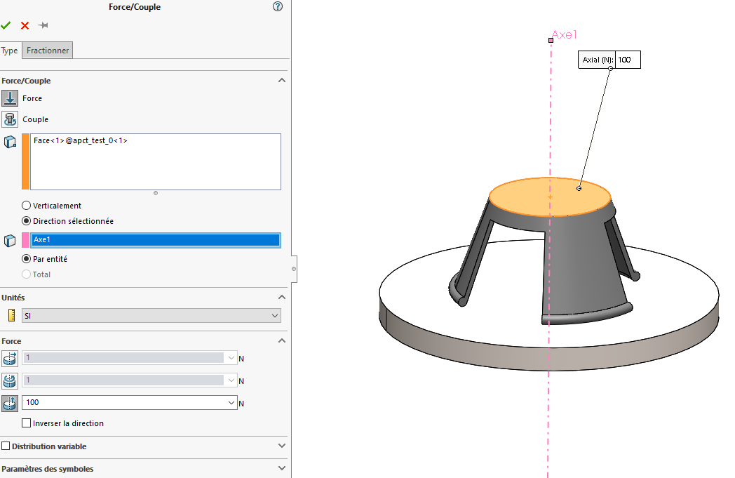
Normalement, si on appuie sur le haut du ‹ tripod ›, les pieds devraient s’écarter vers l’extérieur.
J’obtiens juste un écrasement. Les pieds restent fixes.
Bonjour;
Votre système est naturellement instable, cela ne sera pas facile d’en obtenir des résultats cohérents.
A votre place j’ajouterai une contrainte de déplacement selon un axe coaxial entre votre surface d’appui (le sol) et de centre de la surface de votre tripode.
Vous auriez plus de réponses possibles en proposant votre modèle dans une version plus ancienne que SW2025.
Depuis la version 2024, Solidworks propose l’option « Enregistrer sous » dans une version plus ancienne…
Merci pour vos réponses. @Maclane :
Où se trouve cette contrainte de déplacement? J’ai essayé tout un tas de ‹ déplacements imposés › mais je ne vois pas comment brider le déplacement axialement. @m_blt :
Les fichiers en 2024: test_2.zip (6,1 Mo)
Comme la pièce est symétrique calculer un1/3 du modèle devrait résoudre pas mal de soucis de stabilité / déplacements non maitrisés.
Sinon SW ne devrait pas avoir de souci à gérer le contact face toroïdale / plan normalement.
NB ; pas besoin de modéliser la pièce du dessous si vous pouvez considérer un plan infiniment rigide. Ca allégera le modèle / calcul
@froussel :
oui, je pourrai tout à fait simuler une partie du modèle mais vu que la réponse globale est étrange, je n’ai aucune confiance dans le résultat d’un segment…
je vais quand même tenter!
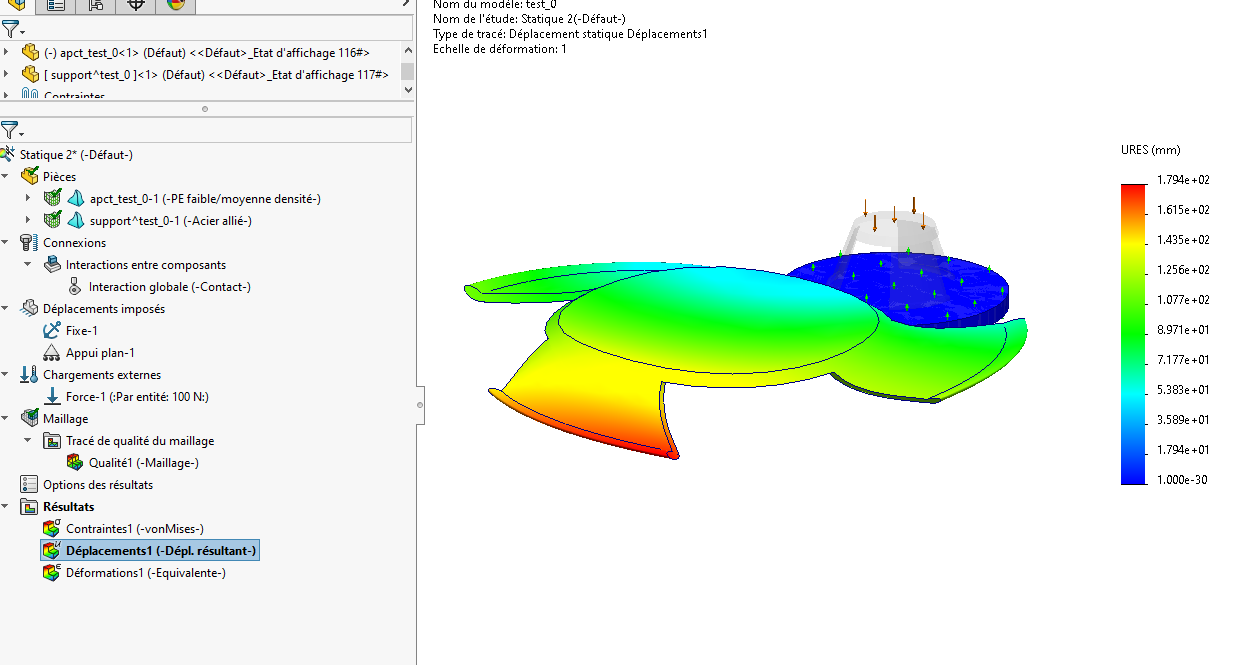
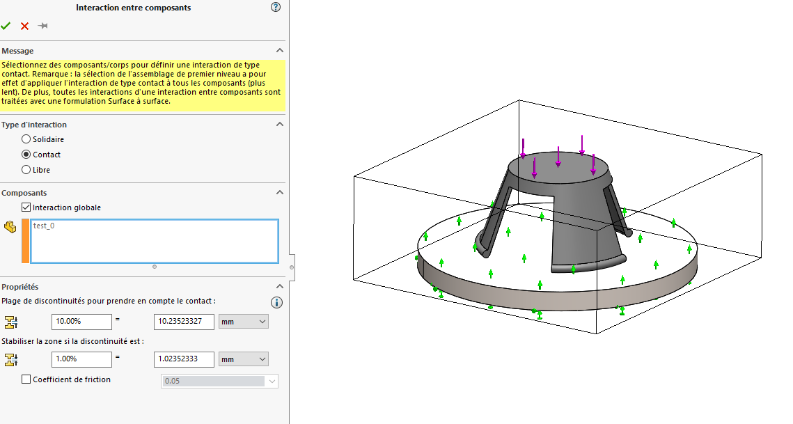
Comme indiqué dans une réponse précédente, le problème vient du fait que les « contacts » du tripode avec le socle ne permettent pas d’assurer son équilibre. Il peut glisser sur le plan, d’où la visualisation des déplacements.
Et ce, même si l’effort appliqué sur la face supérieure est vertical, et n’induit pas de composante provoquant ce déplacement. La faute à la discrétisation du modèle.
La réponse consiste à imposer des contraintes de déplacement pour immobiliser le tripode. Pas toujours facile…
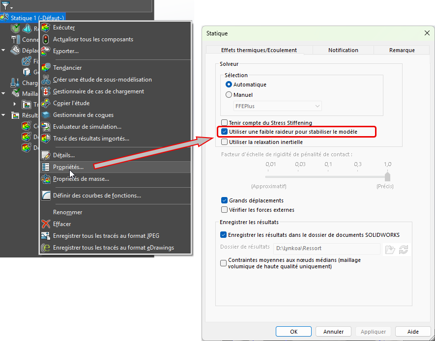
Une solution plus simple consiste à introduire une légère « raideur » venant de l’extérieur pour assurer l’équilibre .
Cette raideur suffit à assurer l’équilibre sans introduire d’effort significatif…
A noter qu’introduire du frottement dans la définition du contact peut aussi résoudre le problème.
Merci à tous et surtout @Walter_POOT !
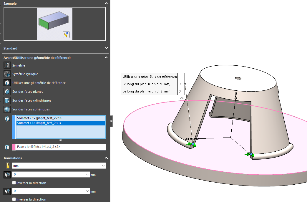
Effectivement, en imposant une géométrie de référence le déplacement devient cohérent (à vérifier tout de même par calculs).
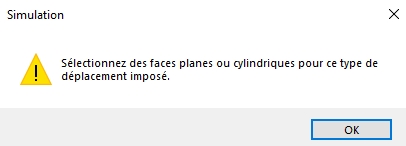
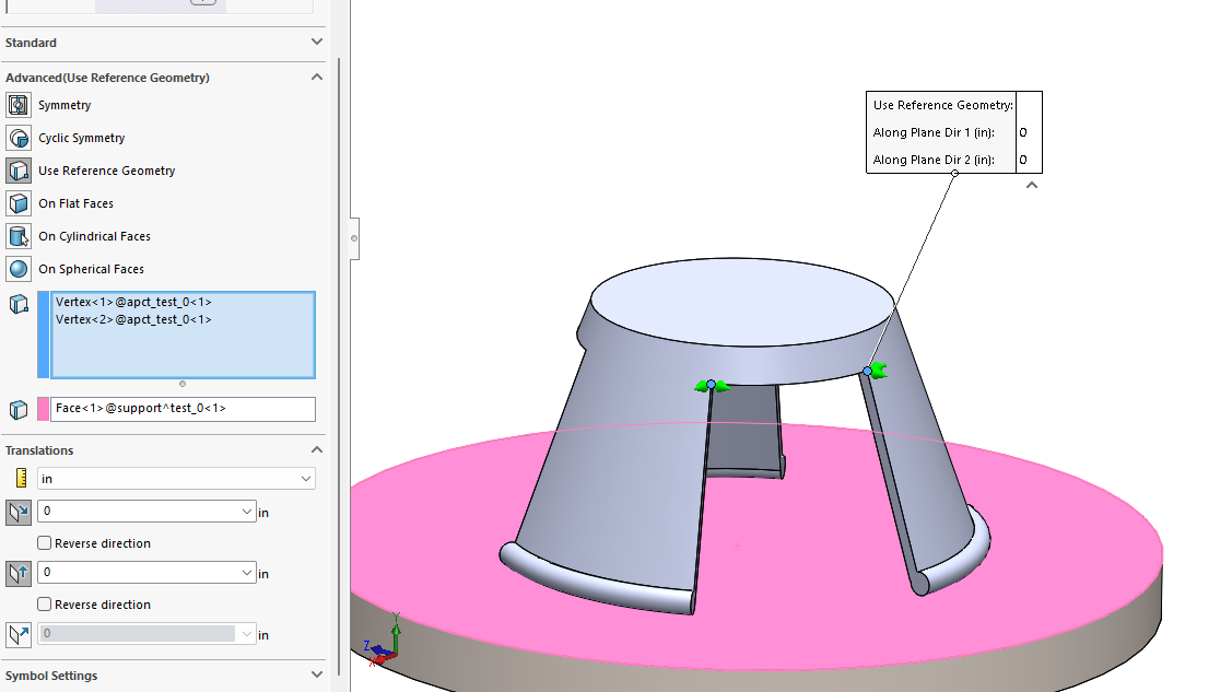
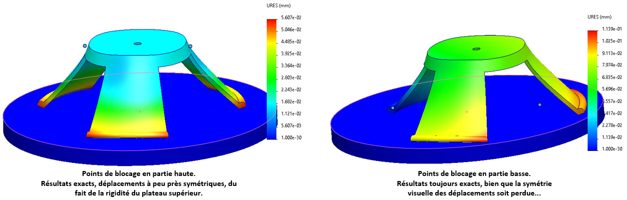
Attention à cette contrainte de déplacement imposé en 2 points, qui justifie ma remarque dans le message précédent :
Contraindre un déplacement nul parallèlement au plan de la base en deux points Impose à la distance les séparant de rester constante lors du chargement.
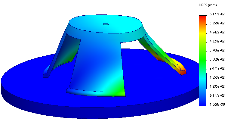
Dans le cas présent, la partie supérieure du tripode est très rigide, ce qui fait que le résultat est proche de la solution exacte.
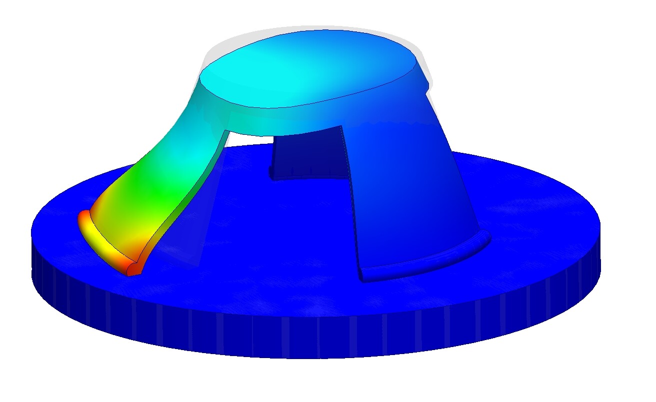
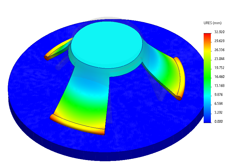
Mais si on applique la même règle à deux autres points, comme sur l’illustration ci-dessous, c’est la distance entre les deux pieds qui est maintenue constante.
Et là, bien que la principe soit le même, le résultat est très différent : peu de déformation des deux pieds de gauche, et déformation beaucoup plus importante du pied de droite.
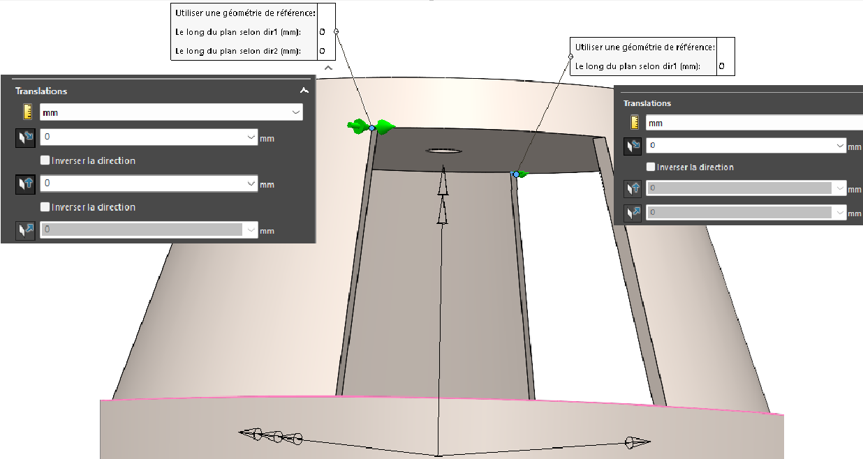
En fait, le contact global tel qu’il est défini dans les interactions laisse au tripode la possibilité d’un mouvement plan (RotY, TrslX, TrslZ), soit 3 degrés de liberté. Il faut donc 3 conditions de déplacement pour l’immobiliser, alors que le modèle proposé en impose quatre, (TrslX, TrslZ) en deux points.
Ma proposition : utiliser deux points diamétralement opposés pour préserver la symétrie du modèle, avec (TrslX, TrslZ) pour le premier et seulement (TrslX) pour le second.
J’ai jeté un coup d’œil à votre configuration de simulation et je pense que je comprends le problème auquel vous êtes confronté. Lorsque vous appuyez sur le haut du trépied, vous vous attendez à ce que les jambes s’étendent vers l’extérieur, un peu comme la base d’un mât de drapeau pourrait se comporter s’il n’était pas correctement ancré. (C’est assez drôle, cela me rappelle comment certains drapeaux américains sur des poteaux flexibles se plient sous le stress du vent - concept similaire, échelle différente !)
D’après votre description, il semble que les conditions limites puissent trop contraindre les pieds. Si les pieds sont « écrasés » mais ne bougent pas vers l’extérieur, vérifiez si :
Vous avez accidentellement fixé trop de degrés de liberté à la base - même de petites contraintes peuvent empêcher le mouvement vers l’extérieur que vous attendez.
Des définitions de contact sont en place entre les pièces si vous utilisez un ensemble - assurez-vous qu’il y a de la place pour un mouvement réaliste.
La géométrie non cylindrique des pieds rend difficile l’utilisation de supports standard « face fixe » ou « roller/slider ». Dans ce cas, envisagez d’utiliser un déplacement à distance ou une géométrie de référence pour simuler un comportement réaliste du pied sans trop le restreindre.
Si vous utilisez SolidWorks Premium, essayez d’utiliser l’analyse statique non linéaire si la déformation est censée être importante.
N’hésitez pas à partager d’autres captures d’écran ou vos détails de configuration, je serai heureux de vous aider.