Complex mechanically welded body: multibody tolerated or assembly of parts?

Hi all

I am currently designing a machine body entirely in sheet metal under SolidWorks (folded sheets, hoods, reinforcements, etc.), and I am wondering about the best way to organize the structure of the model.

Rather than making all the sheet metal parts one by one (.sldprt by .sldprt) to assemble them later, I'm thinking of a "mixed" approach:

Assemblies of interwelded sheets (e.g. the frame) would be modelled as multi-body welded parts. (Each welded group = 1 multibody part file.)
Parts that are not welded, but simply attached to the mechanically welded assembly (by screws, bolts, rivets, inserts, gluing, etc.) would remain as classic separate parts, inserted into an assembly with the multibody parts.

The idea would therefore be to have:

Welded sub-assemblies managed in multibody parts (with their drawing (part by piece + tolerances and weld marks at the part level),
Then a global assembly that includes:

  • mechanically welded multibody parts (sheets welded together),
    - independent non-welded parts (clipped housing, screwed part, glued support, etc.),
    - Screws / bolts.

My questions:

Does this mixed approach (multibody for the welded assemblies + separate parts for the rest) seem coherent and "clean" in practice?
Do you see any advantages/disadvantages to doing like this, especially for:
Drawings,
Tolerance management,
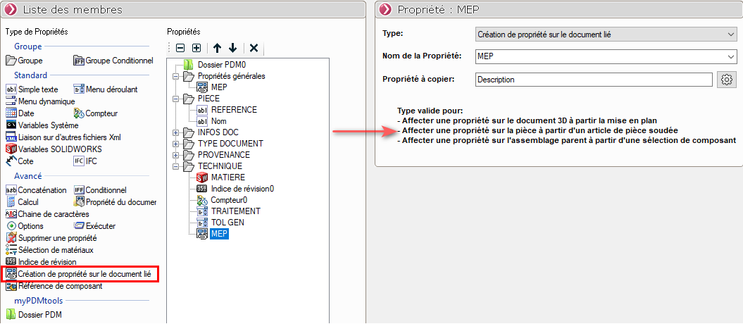
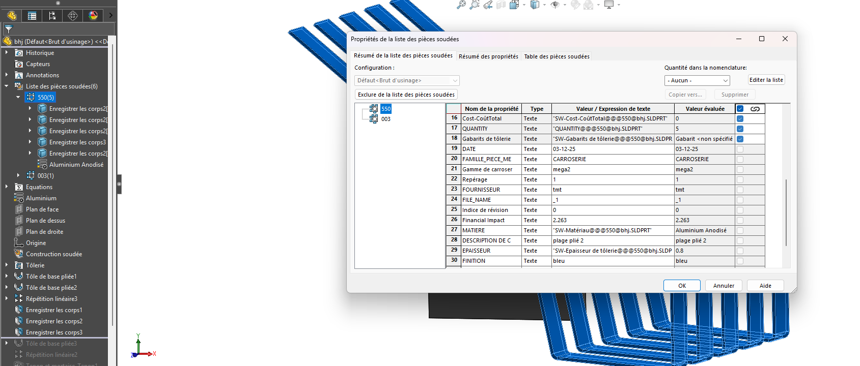
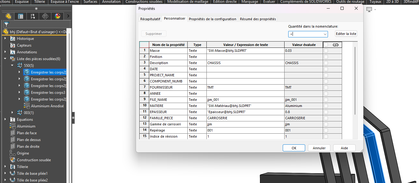
The nomenclature (BOM),
Manufacturing/assembly,
Plan and 3D exports. WWTP for my subcontractor Trôle

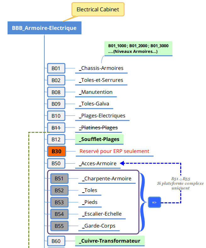
Do you have any feedback or best practices on how to structure this type of project (organization of files, division of welded sub-assemblies, naming, etc.)?

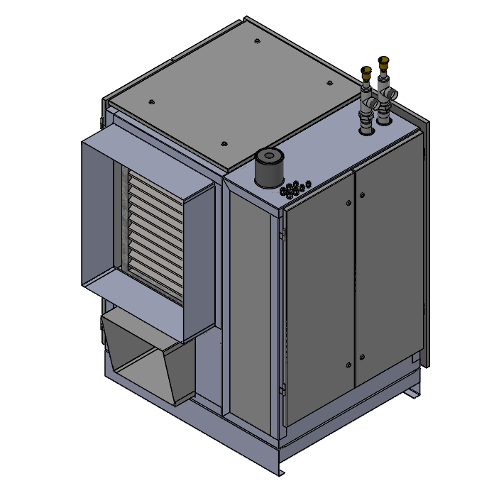
Below is a small image of the current set that I will redesign.
There are almost 100 different sheet metal parts in the set.
image

Thank you in advance for your feedback and ideas!

Hello;
For me, the approach envisaged seems rather relevant to me, at least in the sense that, well, it is the one we use in our society. :sweat_smile:
with a filename structure such as:

XXXXX-1BBB_0000 for complete assembly
(XXXX being our number assigned to the case=> invariable)
and
(1BBB corresponds to:
1=the amount of this component in the assembly
and BBB, the type of the assembly - e.g. group BBB is " Ventilation ")

In this XXXXX-1BBB_0000 Assembly, we would have:
Sub-Assembly XXXXX-1A01_1000 => Mechanically welded assembly + welded components. which would include:
component XXXXX-1B01_1001 =>Mechanically welded bodies (the chassis) +
component XXXXX-1B01_1002 =>Mechanically welded bodies (bracon)
then
Sub-Assembly XXXXX-1B02_1000 => Door and Left Hinge Assembly
Including XXXXX-1B02_1001 door sheet
then
then
Sub-Assembly XXXXX-1B02_2000 => Door and Right Hinge Assembly
Including XXXXX-1B02_2001 door sheet

Roughly speaking, here is our hierarchy of directories and therefore file names:

Each part has a unique layout with the same name as the 3D component (saved in the same directory). + Simple bill of materials with a quantity of parts to be produced.
Each assembly has a drawing with the same name + Detailed BOM + Revision.
The validation of a drawing implies under the index and the editing of a PDF => File Name + Revision in progress.
(Unfortunately, we don't have an ERP...)

Uh, there you have it... I'm not sure I was clear (I have a hard time reading myself ... :upside_down_face:)

But to sum up: Yes, I think your approach is in the right direction.

Kind regards.

4 Likes

Hello

Except for filename conventions, this method is also used in my company.
I therefore agree with @Maclane with a favourable opinion!

2 Likes

Hello
whatever happens 2 bolted, riveted parts... It's assembly on both sides (except in the preliminary project to present a small mechanism, you can do everything in one part).
After the mechanically welded assemblies there are 2 schools; Multi-body or Assembly of mechanical parts.
You can even mix, like in multi-body you would have a profile chassis (Tube, angle, HEA...) and it's practical because the adjust function makes sense, and then in an assembly you add the plates, gusset, sheets, nut to be welded. It's really not bad in case for a case you have to reuse the same turntable for example. You will be able to extract a complete BOM. In the case of multi-body if in your case you have for example 10 different sets with the same bodies, in the end it's always a bit of a hassle to recover the quantities without going through excel.
For referencing it's specific to each BE, we all have our own digit to find our way around the book :sweat_smile:

2 Likes

Hello @theo_meyer

When I make special machines or other electric/mecha/cauldron containers etc, I plan the sub-assemblies by trade, in the spirit of what @Maclane does.

For the design it is specific to your modeling method, personally in your case I plan a common skeleton for all the sub-assemblies to be able to insert them or see fit in drawing presentations (Environment). See the link below:

Assembly1.SLDASM (1.0 MB)

Don't forget that in a machine of this type there will be a lot of step screws so there are a lot of constraints, and external constraints just as numerous. So you have to design intelligently so that you don't have everything that farts at the wrong time :sweat_smile: .

So the skeleton method and a rigorously studied codification downstream.

In addition, even if SolidWorks makes us bills of materials, I imposed a bill of materials on Excel to start with, thus avoiding putting long names on the files, and allowing us not to have duplicate codification.
Subsequently, as a matter of course, it allowed us to fill in custom properties for our BOM and cartridge via a macro.

My opinion, good luck

1 Like

Thank you very much for your answer:+1::+1:, I take note, of a file assembly as you explain to simplify the exports of multibody parts and assemblies to be as clear as possible internally and for subcontractors it's great.

Thank you for your answer :+1:

Thank you for your answer, it's true that the BOM part is a problem for me because I don't know if the multibodies are counted piece by piece in the nomenclature exports on SMARTBOM of the mycadtool

Thank you very much for your answer😁

1 Like

:wink:

We don't make this kind of part, but the multi-body sheet metal part risks having an ultra-long and incomprehensible creation tree.
A variant could be an assembly with pilot sketch and virtual parts. It complicates the MEP a bit (because the rooms are virtual), but it will greatly clarify the creation tree.
The 2 approaches can possibly coexist: multibody sheet metal parts for simple parts (with 4 or 5 sheets that are not too complicated) and assembly with virtual parts (for those with dozens of complex sheets welded together).

2 Likes

Thank you very much for your answers.

After some thought, I'm going to go back to the SmartProperties setup in order to standardize the references and have something cleaner.

For the design part of sheet metal assemblies:

  • some sheet metal parts will be modelled as unibodies,
  • Some small assemblies (maximum 6 different sheets) will be modelled in multibody.

For the management of unibody parts in the BOM and bodies from multibody parts, I will use SmartBom, which will allow me to export the bodies with the properties that I will have defined via SmartProperties.

For 3D/2D drawings and exports, I plan to use the "Save Bodies" feature in SOLIDWORKS: each sheet metal body will be saved as a bonded unibody part. I will be able to create unfolded drawings and STEP exports from these parts, while keeping the link with the original multibody part.

Now I just need to find a way to automatically apply the properties of a body to the bound unibody part.

If anyone has a method or a lead to do this, I'm all for it.

It seems to me that Smartproperties allows the redistribution of properties to welded parts items... but I never tested it.
image

Yes, I use this option for flooding my bodies on a part basis, but when saving bodies, similar bodies are separated into different parts and the properties are not exported because the properties are applied to the sheet metal welded parts list and not to the body itself.
image
image

1 Like