Is it possible to chamfer a volume of a specific height (or width) along a specific axis, so that the distance is a height?
To be clearer, if I apply a chamfer of the same distance on 2 faces with a different angle of inclination, it inevitably creates a height shift.
The only trick I found to achieve the desired result is to create straight extrusions of the desired chamfer height, then chamfer the edges of this extrusion:
And there I have chamfers of heights equal to their distance.
But it forces you to add extrusions so it's not ideal either. So if you have a better solution, I'm all for it.
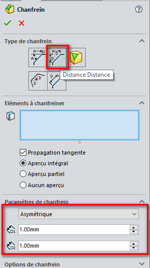
Bah! I didn't understand everything in your demonstration but: In the chamfer options, why not try with Distance/Distance + Asymmetrical to have greater control over the dimensions?
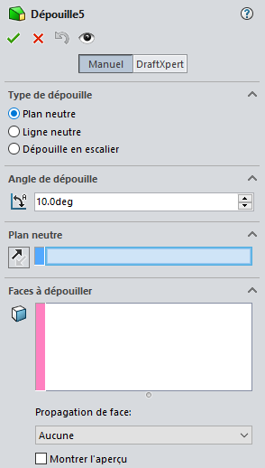
Otherwise try the spoils (with a common neutral plan)
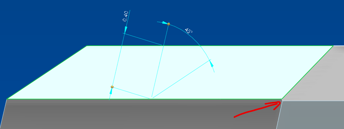
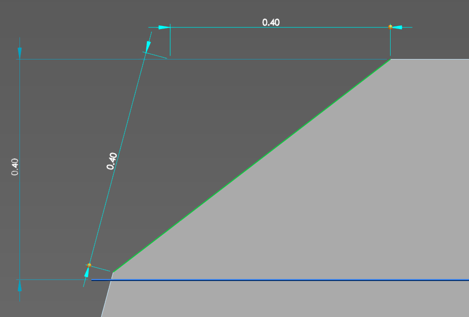
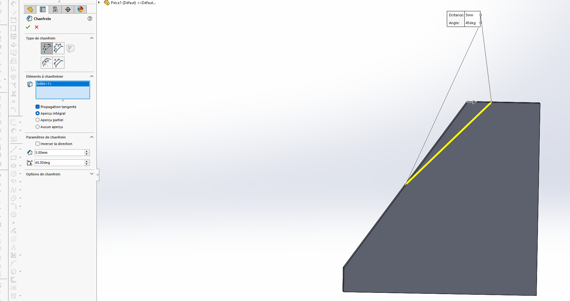
As you can see on the 2nd image, the distance of the chamfer is not parallel to the vertical plane, it is parallel to the inclined face. I want to be able to set a vertical or horizontal distance.
Because the problem remains the same. The distance remains based on the inclination of the face and not on a straight axis/plane.
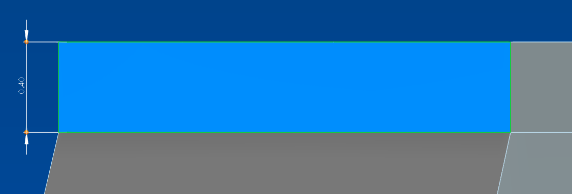
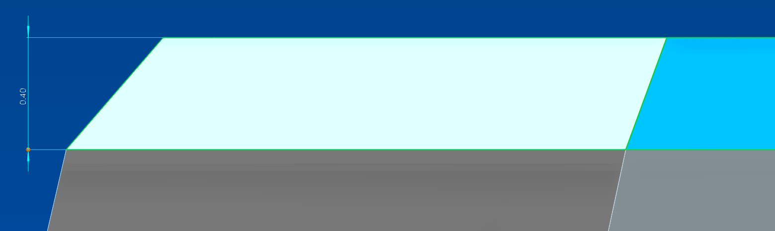
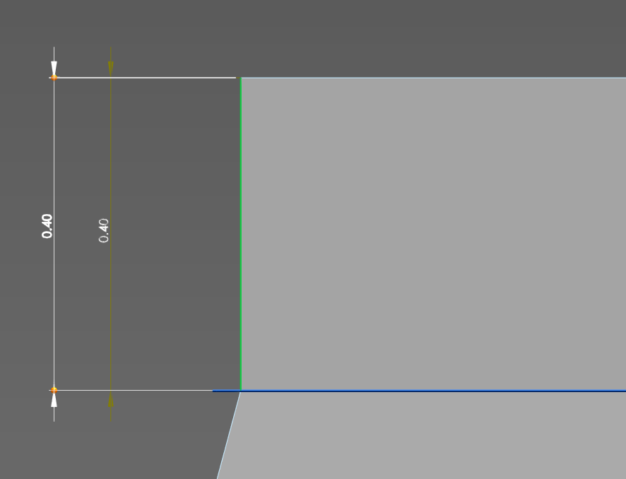
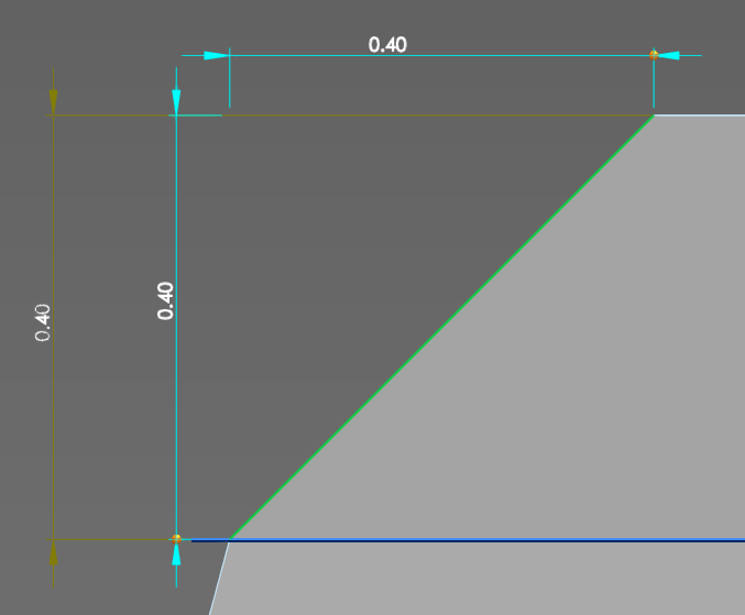
In this image the horizontal line of the plane is indeed 0.4 from the top of the piece, but the height of the chamfer is not, since its reference frame is different:
So I need to add a right-angle extrusion of 0.4 in height:
To apply the chamfer to an edge at a right angle, so that its reference frame is indeed a vertical face:
I'm looking for a way to avoid having to make a right angle to each edge to be chamfered.
The thing is that it doesn't only concern the drafts but all the inclined faces, whether they are by extruded profile, draft or other.
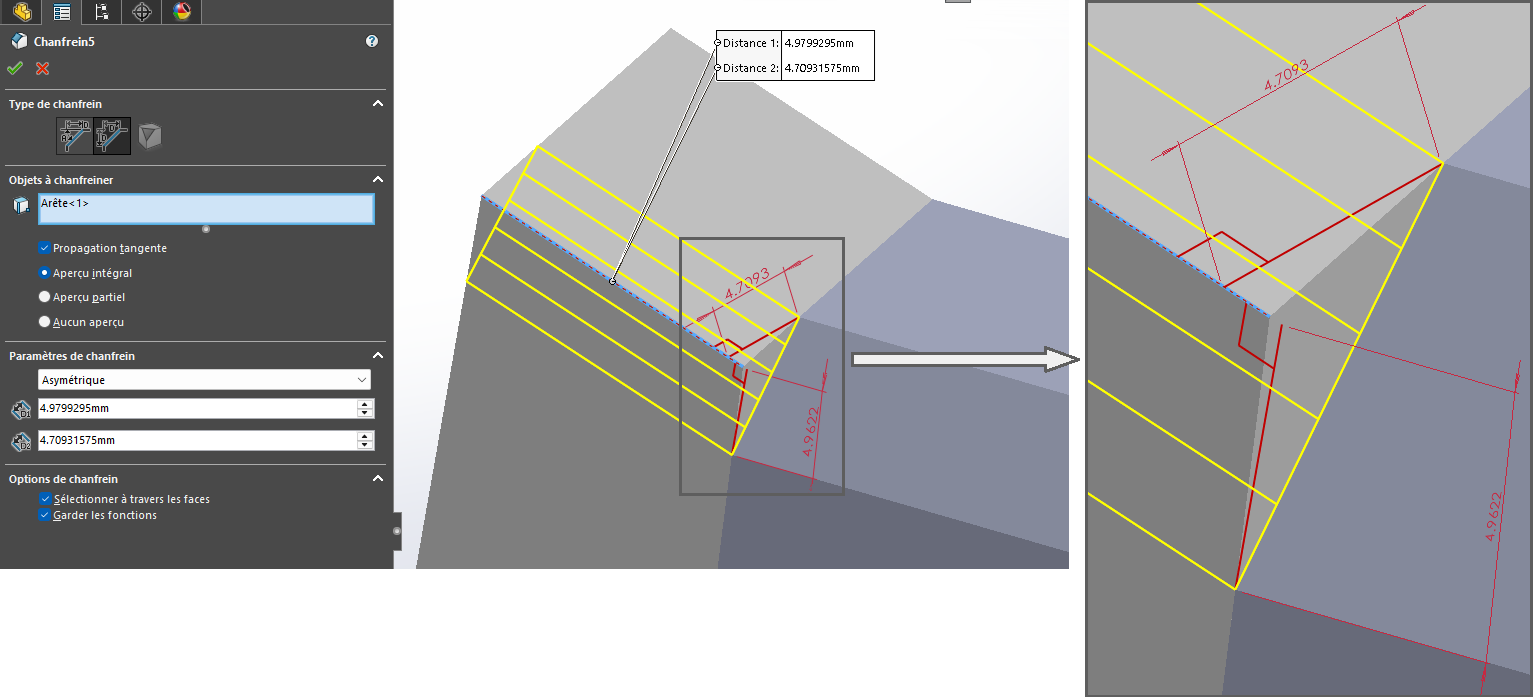
As @Maclane says, the solution probably lies in the asymmetrical chamfer by defining the two dimensions. All you have to do is measure them beforehand on the first chamfer created. This is the role of my 3D sketch (in red) which allows me to define the normal distances from the boundary points of the first chamfer to the edge of the future second chamfer. The 3D sketch only serves to illustrate the point. A simple measurement of the two dimensions is enough to inform creation...
I had thought about calculation/measurement but not convinced; It's not very practical when you have to change the value. My right angle method is not perfect but at least by linking extrusion height and chamfer distance I can freely change the value of the chamfer, and use the angular mode.
Have you tried with a normal chamfer on the first component and then a recovery of the resulting shape into a sketch + removal of material according to trajectory? … (hum!) Now that I think about it, a single removal of matter according to a trajectory should be suitable for all bodies...
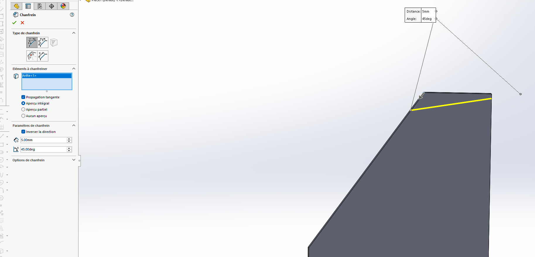
Hello. A bit of a stupid question but... Have you tried by " reversing the steering "? This allows you to put yourself on the right angle in relation to the horizontal/vertical face
@Maclane t on this project but yes, triangle sketch aligned with the piece and then removal of material, that's exactly what I've always done so far. But in the end it's not much better than extrusion+chamfer (except for 1 edge where there is no need for a trajectory).
@coin37coin yes, of course. The problem is not to manage the angle but to obtain a vertical management of the distance. I would have liked a button among the others that would allow a " right angle" mode, but it will obviously never happen, whether you ask for it or not (especially if it's only me who is interested, since obviously it doesn't pose a problem to anyone)...