Hello, I am modeling a lift table and the constraint I put between my rolling and my angle prevents movement.
It's a tangency constraint because I can't put another constraint because it seems to me that it's a sliding pivot that I should have.
Could someone help me?
Hello
If the principle of the table is what I imagine (see image below), there is no reason to obtain a blocking of the movement by imposing a tangency constraint between the roller and the angle.
Movement must be possible...
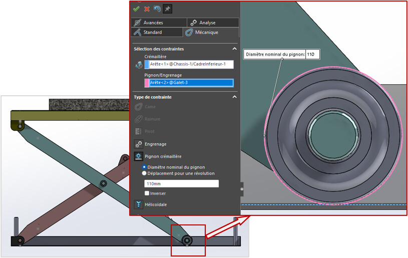
Possible, but without the property of a non-slip bearing between rotation and roller translation. To have this relationship, it is sufficient to define a " Mechanical " constraint, of the " Rack and pinion " type between the two parts.
That's how it is in Solidworks.
Thank you very much for this information I tried the contact between surface and who did not allow me this connection.
I'll try again with this method.
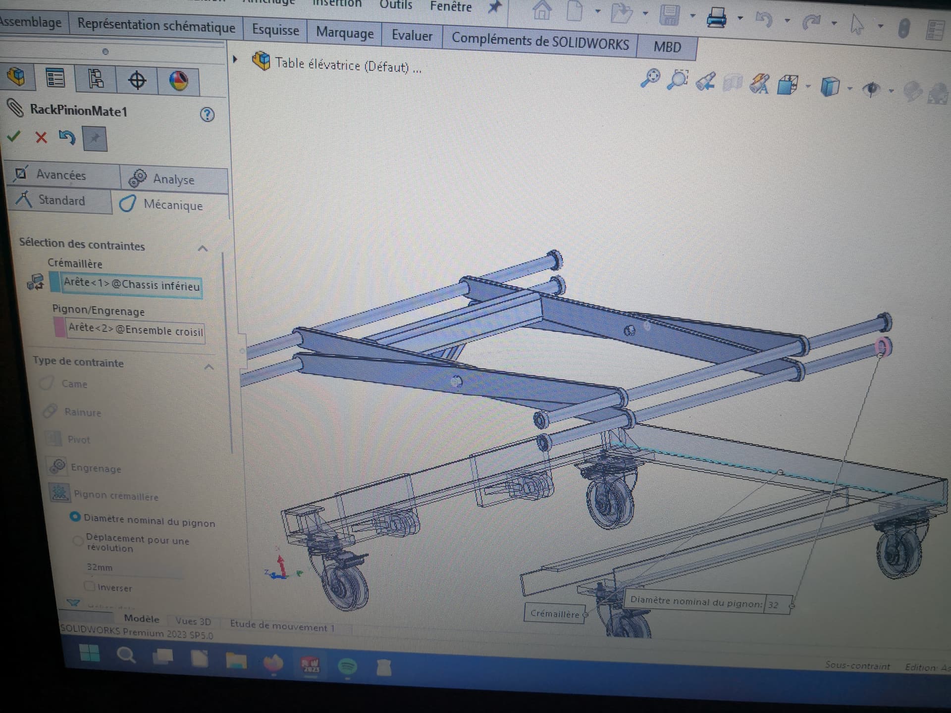
I managed with your method to find this relationship but after creating it the bearing doesn't come to land on my angle, there must be something else that I don't do well.
Sorry to ask questions can be stupid but it's been a very long time since I had touched SW.
Must:
- a tangency constraint to enforce contact between the roller and the angle, and
- a rack and pinion constraint to obtain the rolling relationship without slippage. This last constraint does not force contact between the two parts.
The curious thing is that the tangency constraint you apply seems to be blocking movement. There are undoubtedly other constraints that are incompatible with mobility.
Hello
You need to limit the first-level constraints as much as possible: so have an assembly of a few sub-assemblies (I'd say 4 to 5 given the photo) and not 800 parts constrained between them at the first level.
Possibly make virtual subassemblies if you don't want to have to manage them.
2 Likes
Impeccable for the info, I'll try tonight when I get home from work with the two constraints mentioned.
For the sub-assemblies now I make them as I make them, I quickly realized that it was a mess otherwise.
I have for this realization several sub-assemblies: the lower table with all the fixing on top and the rollers for the movement of the table, the crossbar assembly with their screws installed plus the axes and the rollers to mount on it, the upper table which also has its fixing and I will put another sub-assembly after when I would have made it a single acting cylinder the fittings and the hydraulic pump.
Given your suggestions, I wonder if I have done my rolls with a tangency connection between my rolling balls and the body.
I don't know if everyone has understood that you also constrain the balls of the bearings in order to make them functional in modeling. What's the point?
![]()
2 Likes
There's no point, it's just that I thought I had to model it like this.
To put the marbles in their housing I think I have to do it like this, after necessarily I can remove this constraint according to your advice but my marbles may move when I move my roll I think.
There are a lot of things that I have to learn precisely to succeed in simple things for you.
I guess you downloaded your bearing from a TRACEPARTS style platform. All you have to do is (but normally this is already the case) to fix the different elements that make up your bearing. To do this, in the feature manager, you right-click on the selected parts and choose the "fix " option. You will then have a small (f) that will appear in front of the part number in the fm
![]()
. It is also possible to save your assembly as an sldprt part.
1 Like
Hello
Sage advice offered by @froussel ...
I would add that a structuring of this type is almost essential for a mobile system, from the perspective of a static or dynamic study.
The main assembly should consist only of sub-assemblies (or parts) that constitute the " kinematic groups" of the mechanism, sub-assemblies of components that are fully interconnected.
There would be 6 in the case of the lift table:
- the chassis;
- the two arms forming the chisel;
- the top tray;
- the two components of the operating system: cylinder body and piston, or screw and nut, or others...
For all the " hardware ", bearings, rollers, castors, screws... the components offered by libraries (Toolbox, Traceparts) or by manufacturers are supplied ready-to-use, in the form of parts or assemblies, without the need to define constraints.
Except for those necessary for their positioning in their destination assembly.
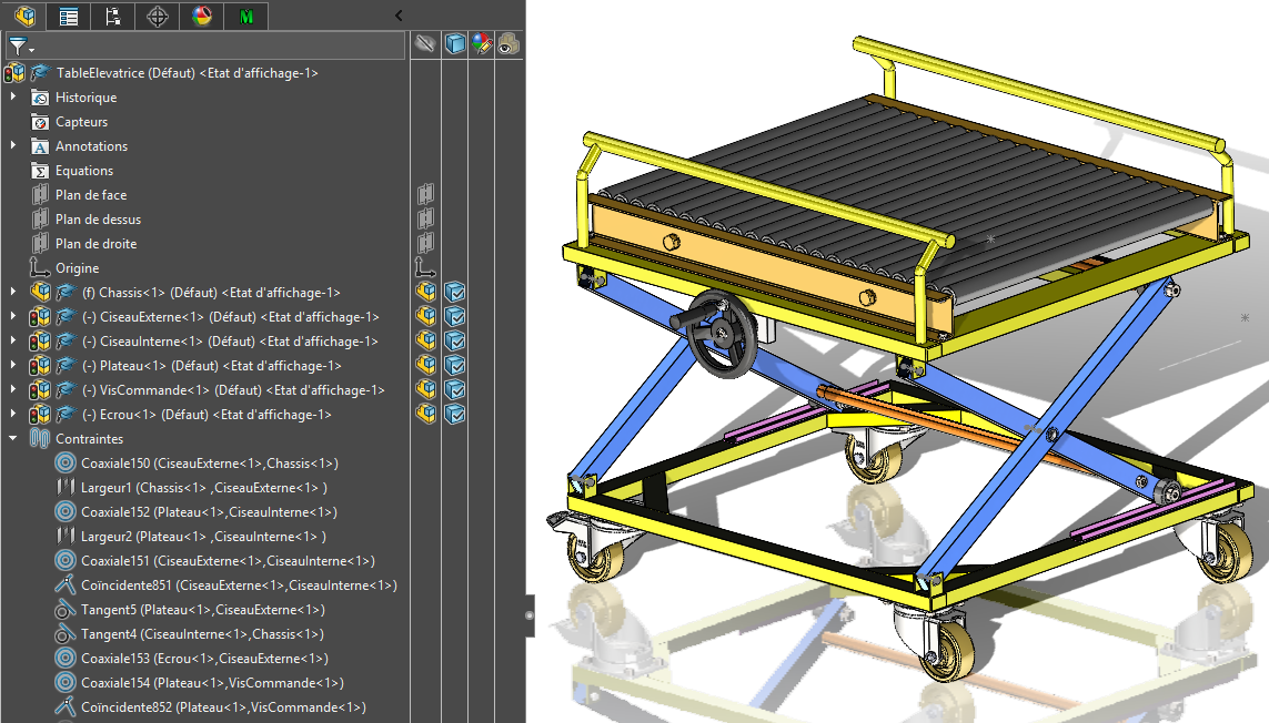
See image below, on a model from Grabcad:
- 6 assemblies on the first level (the parts in the mechanical sense of the term),
- and only 11 constraints to position them.
Note that the rollers are integrated into the assemblies of the chisel arms, and the rollers in the frame. There is no real interest in making them mobile sub-assemblies...
1 Like
So no, the necessary rolls, I'm not DL, I force myself to do as many pieces as possible by myself to learn.
So your advice is really useful to me, so if I understand correctly I use the constraints to set up my rolling balls and then I fix them which will allow me to remove the constraints blocking the movement.
I am now trying to favor sub-assemblies.
I was going to try all this this lunch at lunchtime.
Thank you everyone
Good evening
In practice, and apart from the bearing manufacturers, generally no one draws the balls or rollers (or a very succinct representation if you want realistic MEPs).
Balls/rollers are of no use to the designer who uses a bearing.
And their representation greatly weighs down the model and the drawings. Even bearing manufacturers give ultra-simplified 3D of their bearings (INA for example only puts 4 rollers on its roller bearings: enough for the majority of cuts).
1 Like
Hello thank you all for your messages, thanks to this I learned that I can have fun creating small assemblies for fun like rolling, piston or other but that for more complex assemblies that need movement I must favor the parts of bookcases which are less heavy for my computer.