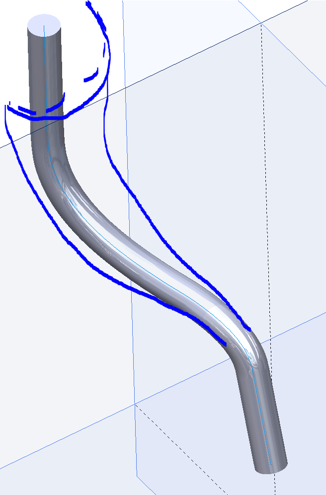
I need to create air reducers, with 3.6mm inlets and 1mm outlets. The curves of the ducts have different layouts but they must respect a maximum reduction angle of 11° (passage angle of 3.6 to 1 mm).
So I've created a swept curve, on which I would like to make a draft that follows this curve. How can I do this?
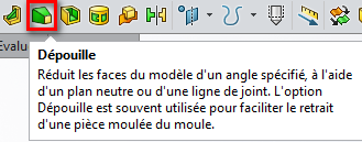
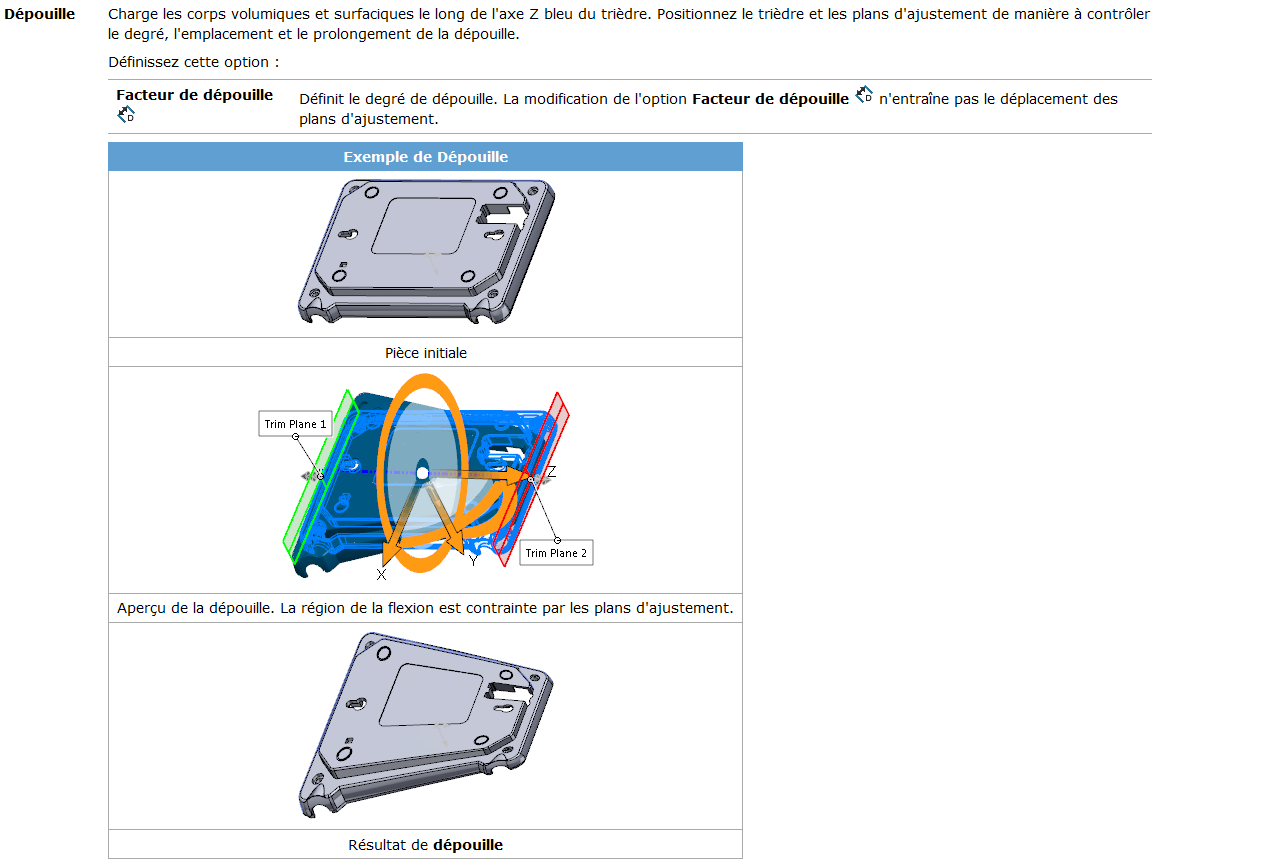
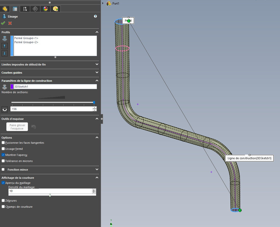
Question to the c... (my question is at the C... not yours @Sylk ) I imagine that the draft function does not work on this type of scan? Otherwise I think you'll have to go through a smoothing through several sketches, or/and with a guide curve offset by the value of the angle https://help.solidworks.com/2022/french/Solidworks/sldworks/HIDD_DVE_FEAT_LOFT.htm?rid=136458 … See also (because it is too often forgotten) the " Flex " tool: Which offers a "Draft" option. although in the form of a factor and not an angle...
The problem with the " strip" function on the curve is that it turns it into a straight line, instead of following the curve
I test with smoothing but the thing is that to adjust the path of the duct I can't be sure of the angle of reduction generated.
Edit: well I'm going to forget the smoothing, this bogus function is not fucked up to follow a curve by the center of the circle, like the swipe does... I can't even define the connectors... or even see them. In no uncertain terms.
Seriously, so complicated to make ONE function that does both at the same time, a smoothed sweep??!
The idea could have been good but the bending draft is not at all suitable for my case, it strips the part in a global way, like in an invisible box.
I just want to flare a tube... but, as always, I feel like I'm asking SW for the moon ...
I still wonder how the industry manages to work with tools that are incapable of such simple things? You can simulate a moon landing with it but you can't connect 2 circles, normal.
The problem with the remains is that they propagate according to a plane orientation and do not necessarily follow a curve. Apart from doing a smoothing by generating all the sketches of passage and a guide curve in 3D sketch that connects the different sections, I don't see.
Well yes but in a straight line You shouldn't ask too much of a parametric software either. I have used Catia (V4) and I have been using SW for years and quite frankly for geometries of this type I have never seen a software interpret it alone without a minimum of data (guide curves, passage sections...)
Hello @Cyril.f I admit that no software does better, but it's always frustrating to spend time doing (or figuring out how) simple things to make the slightest idea come true.
I also admit that I can foolishly drive myself crazy by missing out on existing functions that I don't know... Well sometimes DIY seems inevitable and that's a shame, not to say damaging.
Toutafè for once! I believe that it is the force of habit; so accustomed to insoluble problems that I end up believing that SW doesn't know how to do anything... unless it's me
Thank you @Silver_Surfer I'm going to try with the construction line, I didn't know this usage.
This technique does not tell me the angle formed by the duct but it has the merit of making the draft by following the curve, which answers the question of the title, so I validate your solution.
Hi @Sylk For the angle you will get it by making a cut of the smoothing obtained and by gluing a tangent line (SW will never give it to you otherwise). Or else you calculate it by hand.