How do you flex a part of a volume without using flex?

Hello

What are the ways to partially fold a volume in a specific place, in a specific area?

Action area between the pink lines
Bending pivot point in orange
Starting axis in green
Axis shown in red

And don't let anyone talk to me about this big bending function that isn't fucked up to have adjustable axis positioning or aligned or alignable centers and that makes me s***.

Thank you

The only solution I had found on a similar case:
Removal of material in the pink area, displacement of the body via rotation (and extrusion to connect the 2 bodies (with fusion)
Not great but not found better, because indeed we can't die that flexion is super optimized...

2 Likes

Thank you for the answer @sbadenis .

Do you think your solution could be animated in a motion study? The goal is to be able to represent a pinch of the 2 symmetrical parts to be flexed, to take the rack out of its housing where it is wedged by the lugs (the kind of dotted pyramids). In summary, the bending must be dynamic.

I knew you were going to make this request next! :rofl: :rofl: :rofl:
I doubt it very much, unfortunately for you.

2 Likes

Unless you manage to change the confi in a movement study and then you go through a straight config and then a distorted config (with one or 2 intermediate configs if necessary to avoid the too jerky effect if necessary)

Why do I always want to do impossible stuff? :triumph: What a serious ball and chain

1 Like

Twisted mind perhaps? torturing your mind like that you're going to end badly, and maybe even as a developer at Dassault for SW!

1 Like

That's for sure in Solidworks it's easier to twist your mind than a volume... :unamused:

1 Like

Hello @Sylk ,

Decidedly, we don't leave each other...
This bending in SW isn't intuitive, but it works. As a rule.

In a sketch, place two points that allow you to locate future adjustment planes.

image

In the bending function, select these two points to position the planes.
Then, play with the 6 parameters of the trihedron:

  • The translations to bring the origin of the trihedron to one of the planes, which will be fixed
  • Rotations to bring the X axis of the trihedron (bending axis) in the desired direction of deformation. The rotations are made around the axes of the general coordinate system.

image

Set the value of the bending angle, or the radius of curvature of the neutral fiber, and you're done.
As for making an animation, I think you have to go through several bodies in a room, or several parts in an assembly.

3 Likes

After the order, always wait for the counter-order.
As is often the case, a macro can be suitable... All you need to do is adapt the name of the function (" Flexion2 ") and the name of the dimension (" D0 ").
It's basic, but it's moving. Not sure that it applies effectively to a somewhat complex set.

Option Explicit

        Dim swApp       As SldWorks.SldWorks
        Dim swModel     As ModelDoc2
        Dim swFeature   As Feature
        Dim swDim       As Dimension

Function ChangeFlexion(nDeb As Integer, nFin As Integer, incr As Double) As Boolean
        Dim i       As Integer
        Dim pas     As Integer
        Dim ret     As Integer
        
    If nFin > nDeb Then pas = 1 Else pas = -1
    For i = nDeb To nFin Step pas
        ret = swDim.SetValue3(i * incr, swSetValue_InThisConfiguration, Nothing)
        swModel.EditRebuild3
        swModel.GraphicsRedraw2
    Next i
End Function

Sub main()
    Set swApp = Application.SldWorks
    Set swModel = swApp.ActiveDoc
    Set swFeature = swModel.FeatureByName("Flexion2")
    Set swDim = swFeature.Parameter("D0")
    ChangeFlexion 0, 30, 0.5
    ChangeFlexion 29, 0, 0.5  ' Valeurs négatives non autorisée
End Sub
4 Likes

Hello @m_blt

The problem is not so much to understand the function as to make it do what it is supposed to do.

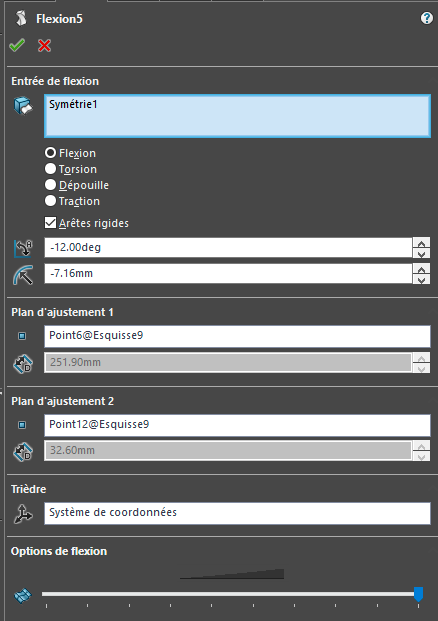
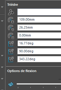
Instead of placing 2 points I just moved the adjustment planes via their value, so when in doubt I used points but no better.

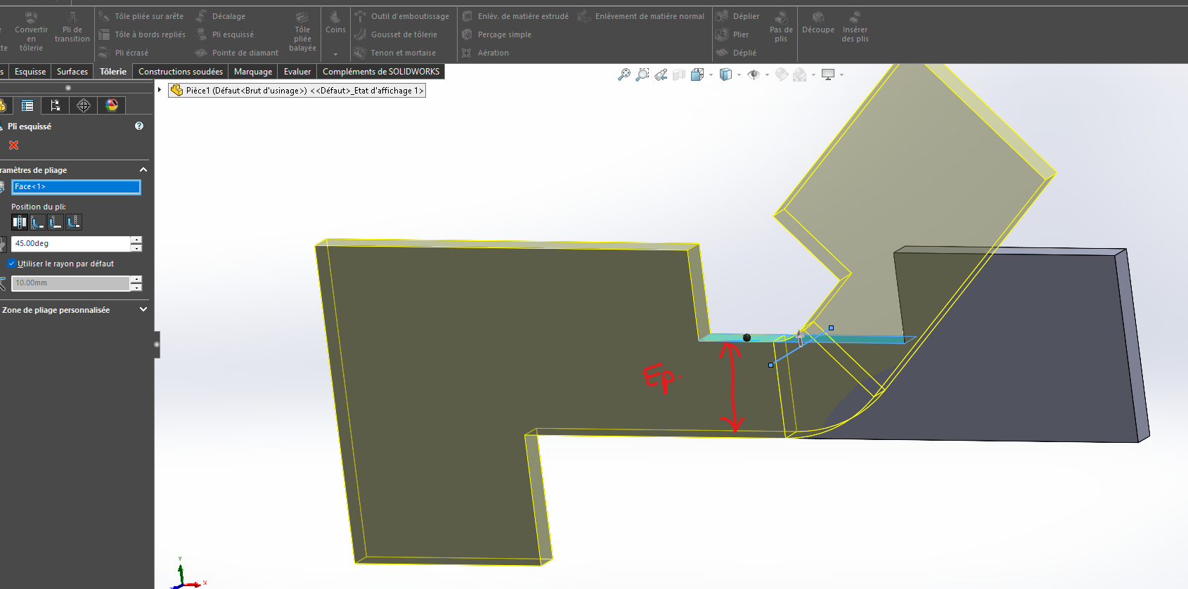
There are several problems with this feature:

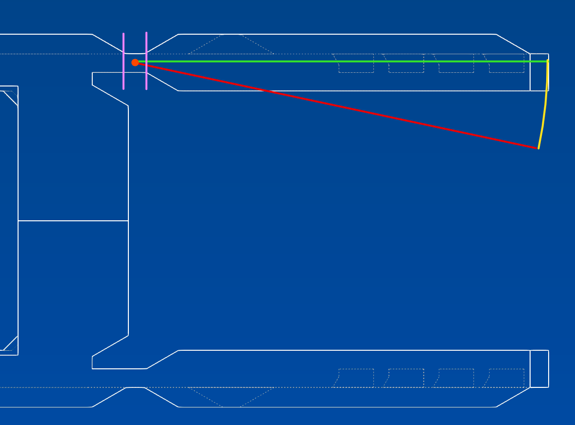
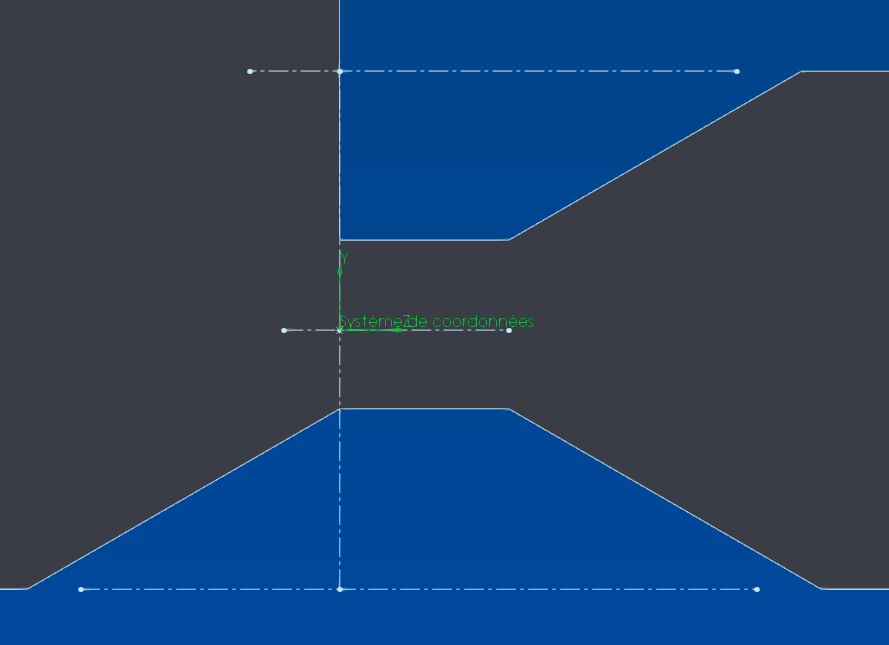
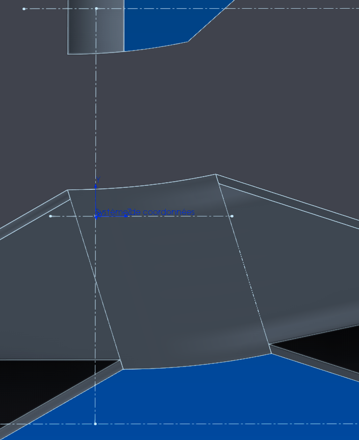
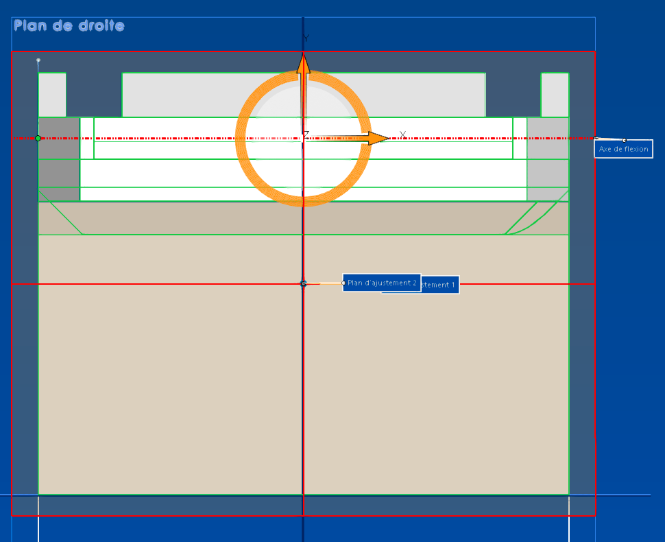
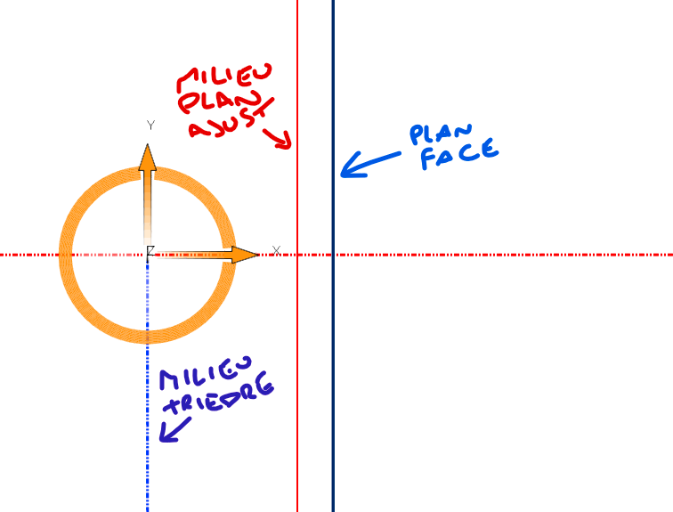
The dimensions of the adjustment planes and their center are not editable, they remain in the middle of the volume, while it is higher that I want to fold it:
image
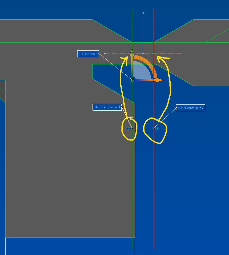
(I know what you're thinking when you see this drawing, but not :rofl: even if it illustrates the path my baloches take with this function...)

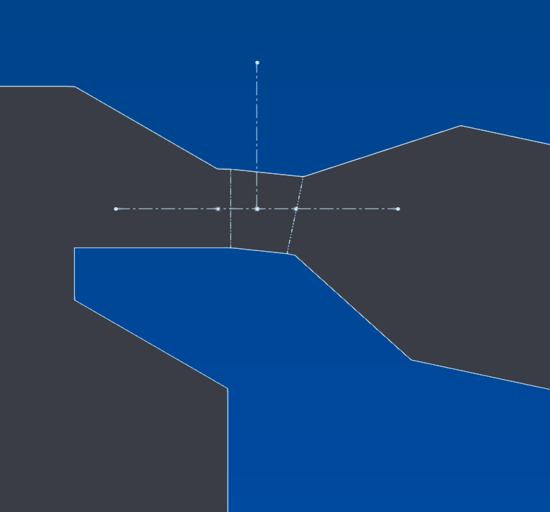
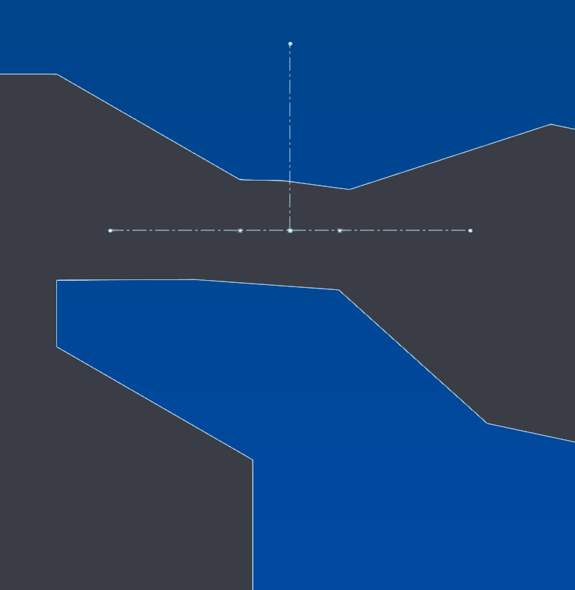
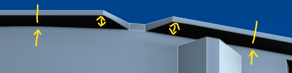
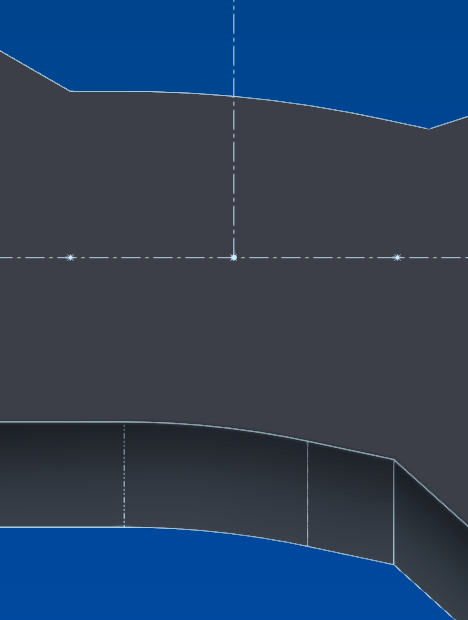
Which has the consequence of distorting the geometry in places where I don't want to:
image

So the walkthrough (or not) to at least not distort these areas is to move the planes to take the bottom part out of the action zone, which already distorts everything, without fixing everything, we see that the bending is always inexact:
image

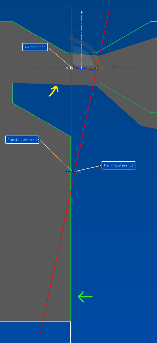
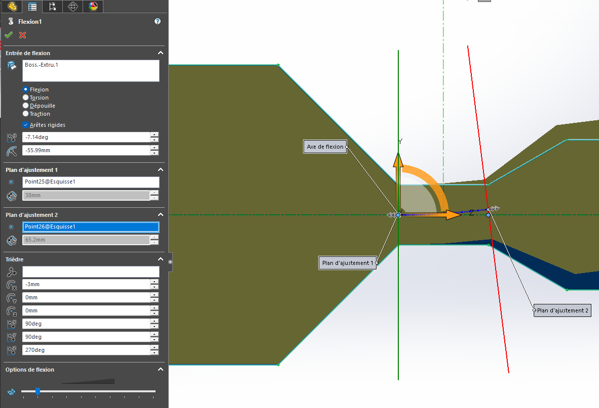
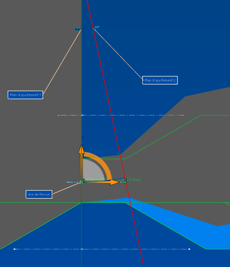
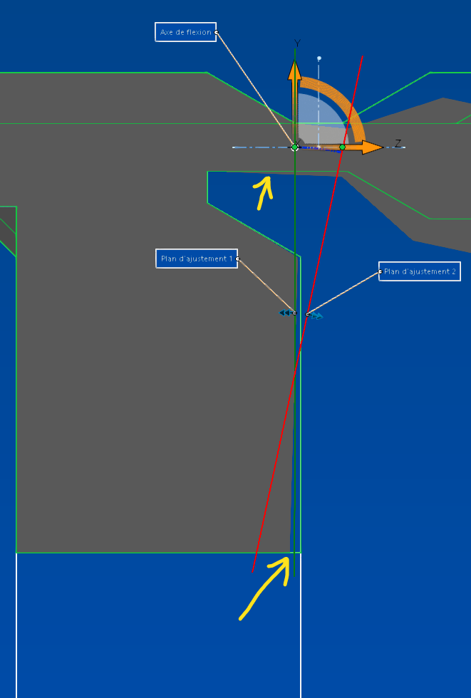
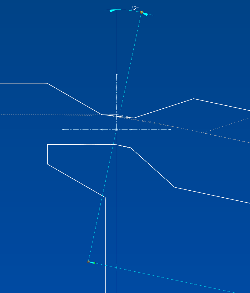
First of all, I don't understand why there are bastard angles in x and z when the part is square:
image

In short, if I validate this with the rigid edges it's not as bad as what I had before, but not great either:
image

If I validate without rigid edges, it's not as bad but not great either:
image

At least if you look at it from the side, because in reality, it's as if only the sides were deformed in smooth mode,
image

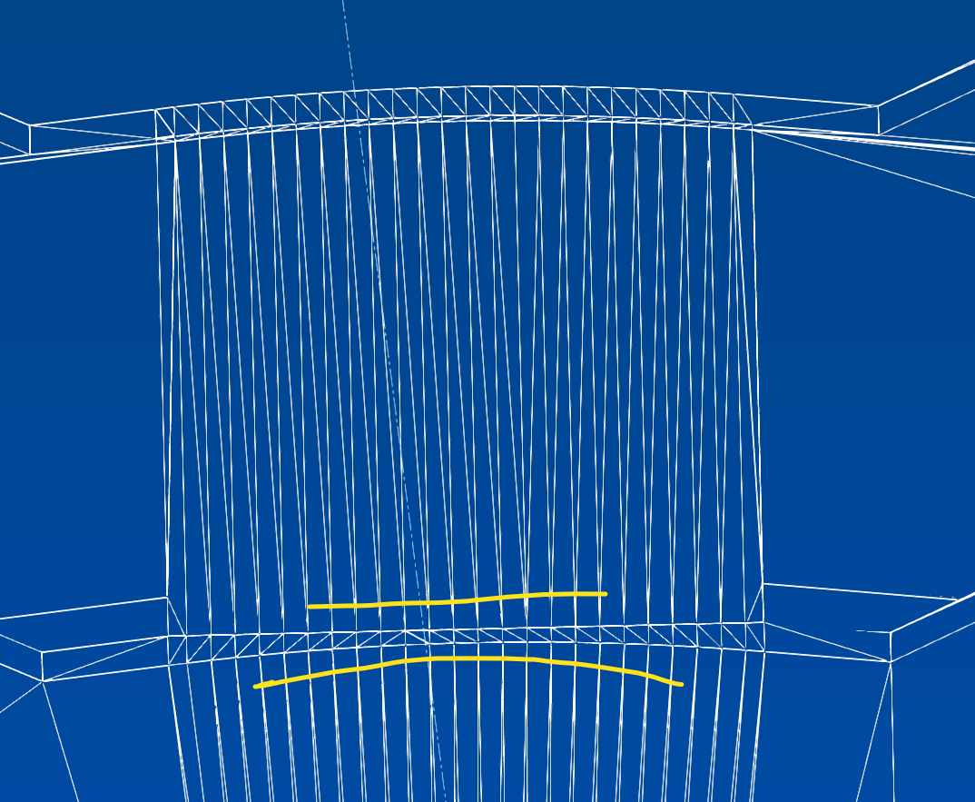
As a bonus, the bending extends well beyond the limits, and all this despite a so-called maximum bending precision:
image
image

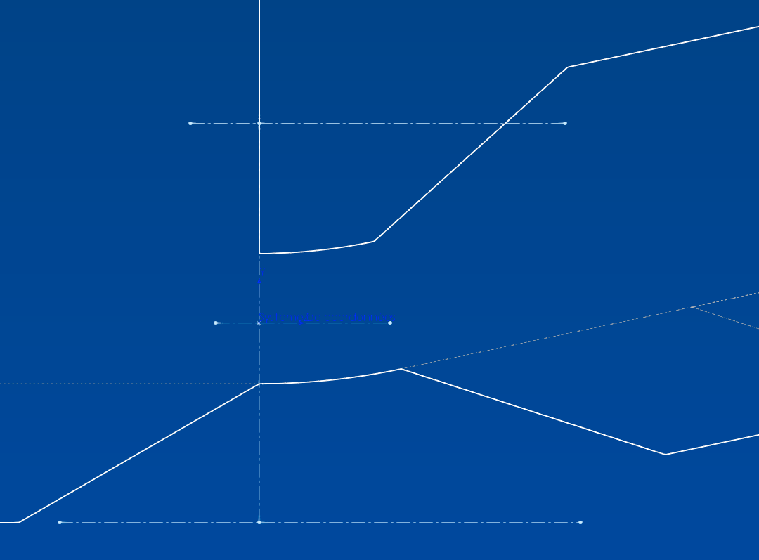
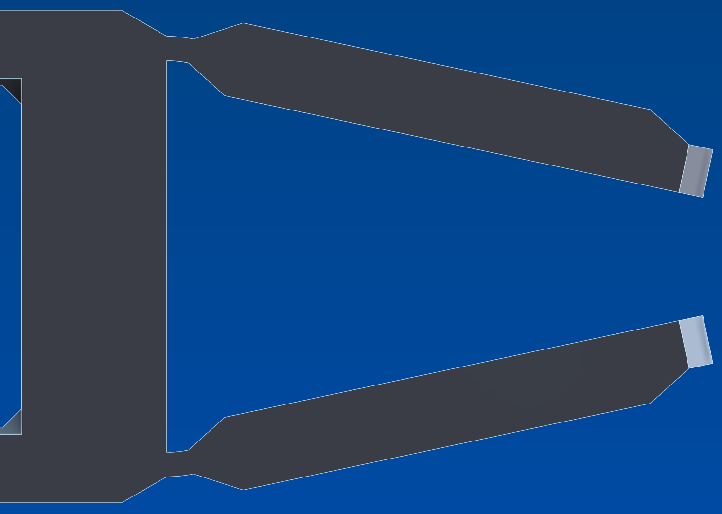
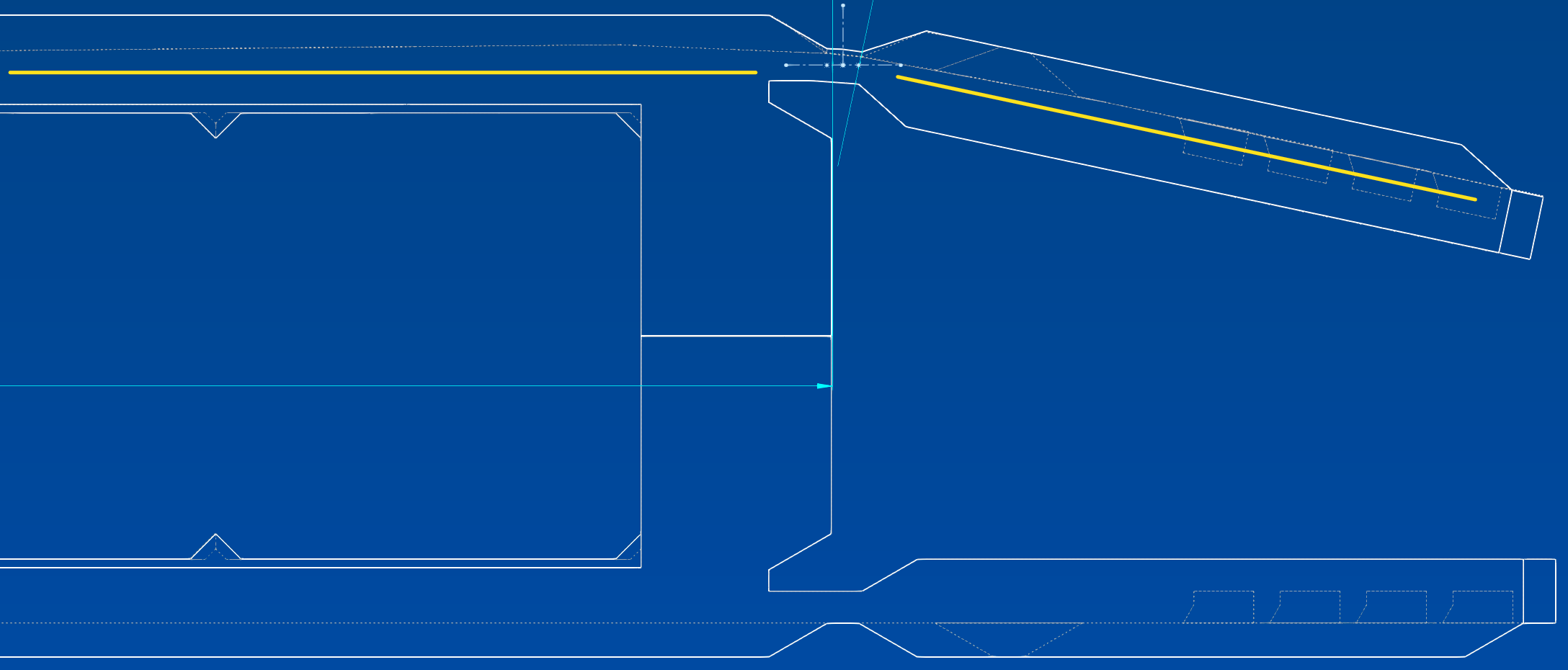
And it has an impact on the entire length of the piece; The inner faces (in dotted lines) are no longer parallel at all, which prevents these faces from being used in the assembly constraints:
image

In the daubé genre it is there, and well there. And it's not over...

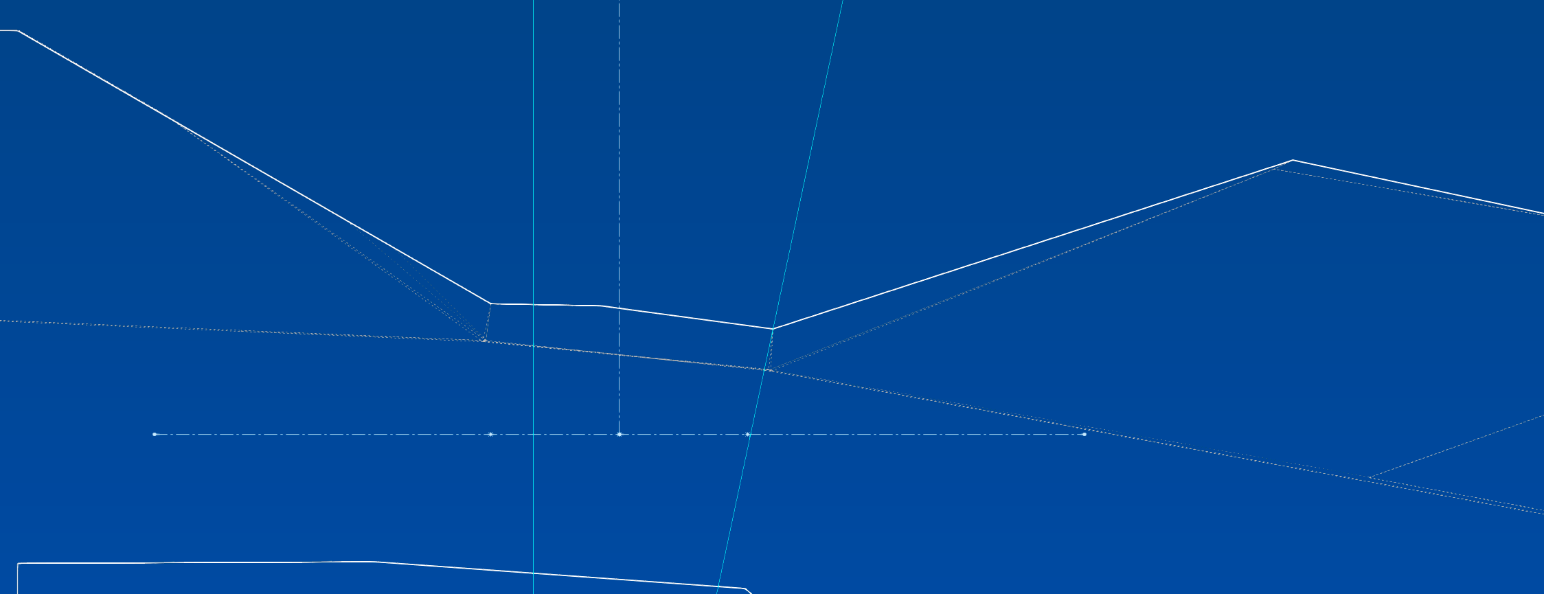
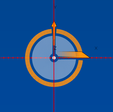
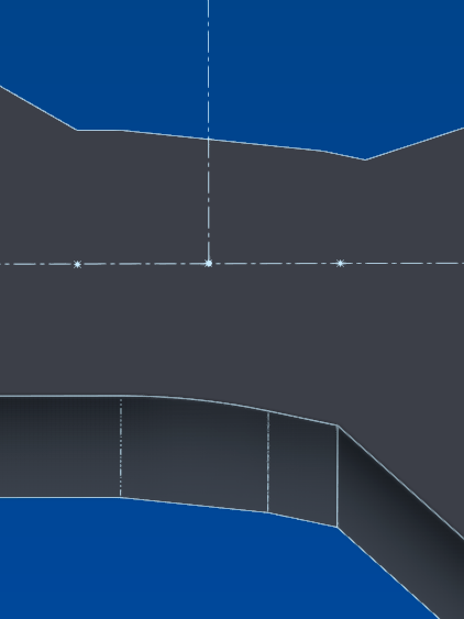
If I look from the right plane, all the axes seem to be well aligned:
image

When in fact, far from it! If we get closer...:
image

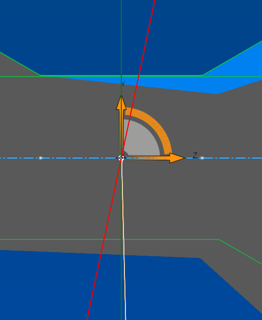
The thing is that the trihedron and therefore the bending axis is placed on the center of mass:
image

And if to regain balance I remove a leave that I had only on one side, all the axes are well aligned:
image

No pun intended, it lacks flexibility as it works.

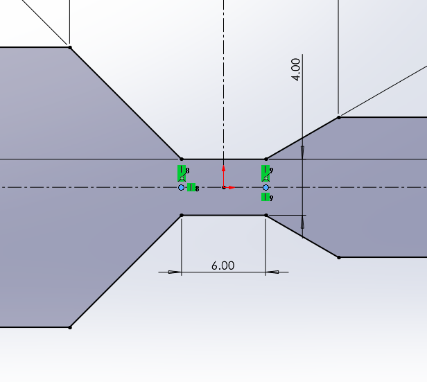
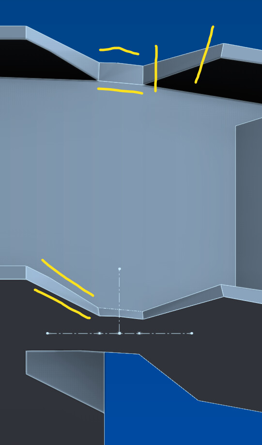
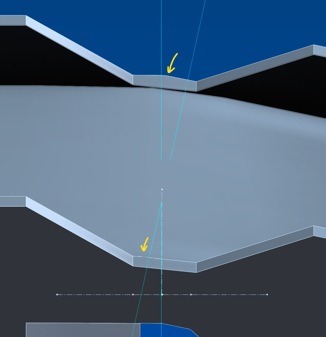
The least worst solution (or not) is to cross the adjustment planes in the center of the area to be folded. Well, almost in the center because impossible:
image

Very far from being perfect but at least the deformations are much less obvious and spread less over the length of the part:
image
image
However, it is not satisfactory... It suggests that with a perfect cross these remnants would disappear, but since that's not possible...

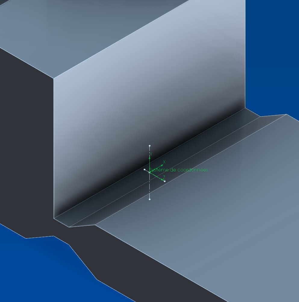
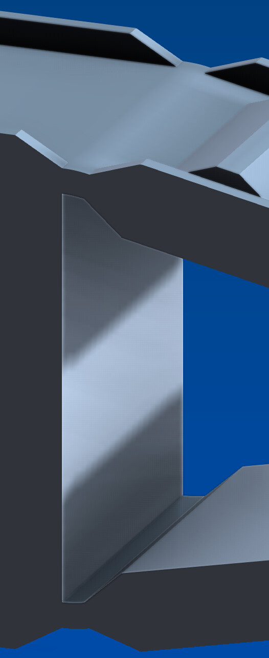
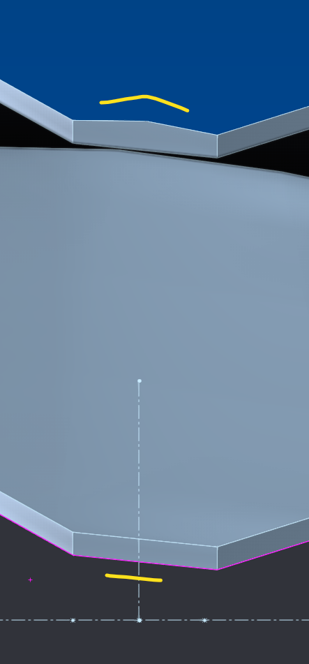
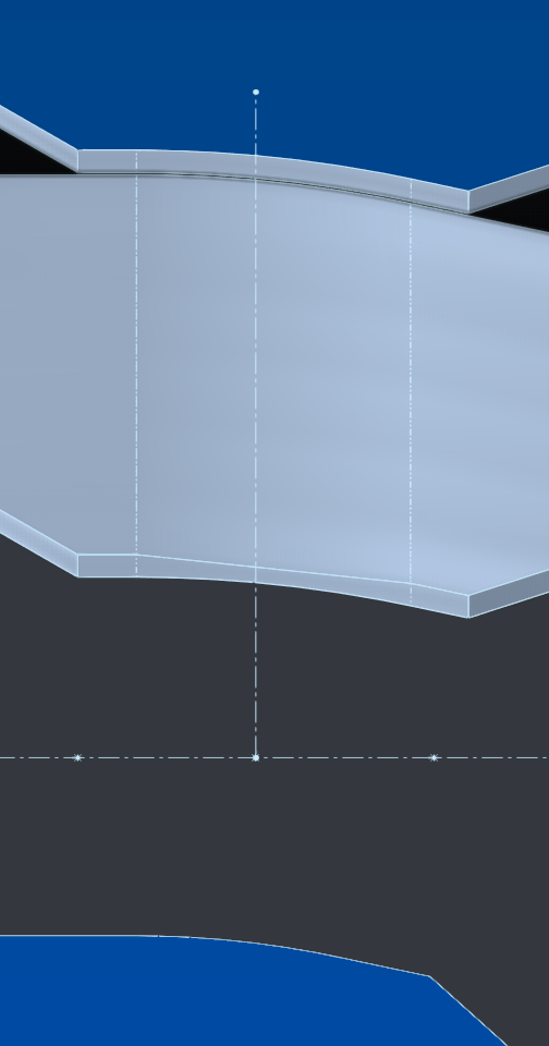
By bringing the crossing point even closer, I manage to eliminate the bottom defect, but the bending remains asymmetrical, with a crease at the top and not at the bottom:
image
Finally... until I increase the image quality of the document to the fullest:
image

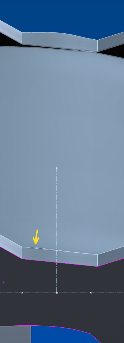
The least worst is with rigid edges, but still asymmetrical, flat in front, folded behind:
image
and underneath it's the opposite, folded in front, flat behind:
image

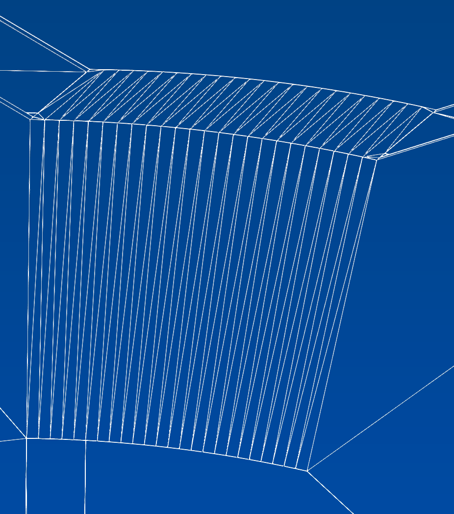
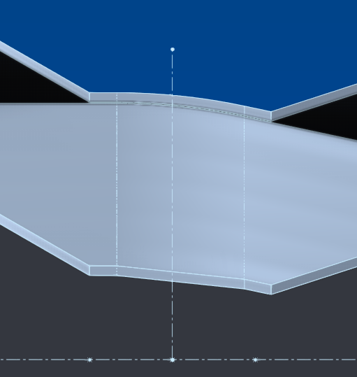
So I think maybe it's just a rendering problem, but when I export it, if one part of the topology can be seen becoming curved, another part remains flat:
image
Enough to drive you crazy...

The craziest thing is that testing the export to see the topology debugged the display which is now compliant with the topo:
image image
Finally... until I refresh the viewport...

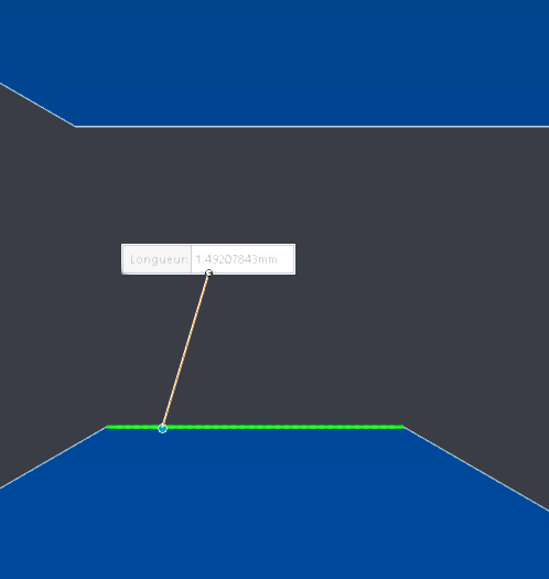
The area to be folded is only 1.5mm so obviously with the degree of precision of the function it doesn't help:
image

Anyway, I'll stop the carnage here, it's s**t. I won't make it like that.

The only way to get something out of it would perhaps be to separate the part to be deformed from the rest of the volume so that all the axes are already aligned with the center of the area to be bent, which implies merging the bodies only after bending... (edit: actually not even). You talk about a solution and a simplification of things...

I'm in 2020 but the most distressing thing is that I'm sure that nothing has changed since then and that it's still the same m#$rde on the 2025... thank you DS!

Thanks for the macro but, as usual, everything works upside down with me :sweat: ; it folds in reverse. And since the macro doesn't allow a negative value, and I can't change the direction of the quote...

Well I modified a few things. Or rather put things back to the way they were at the beginning.

Geometry:
I removed the small offset* of the ramp, which I had put just to try to use the cam constraint but in vain. It's always that much less geometry to calculate for bending.
I directly merged the ramps with the rest, instead of recombining them.
I applied the flexion before the second symmetry of the body. And so on the bottom tongue, which changes the direction of the angle dimension.

As for the settings, I set a coordinate system on the coordinate systems, with the Z on the X line since the bending is applied according to the X axis (But that's just to simplify the positioning of the trihedron, because it doesn't change the bugs):
image
image
image
image

And there, it folds cleanly and evenly:
image
image

After second symmetry, the geometry remains correct:
image
image

And this time the topology is perfect:
image

It's not a shame!

Conclusion:
3 possible causes of the problem;

  • the overly complex geometry generated by the shift, but I doubt it since she managed to apply it cleanly on one side.
  • The topology generated by the combine function that the bending does not know how to work.
  • the orientation of the bending, which was with a positive angle.

I am inclined to the second, without certainty.

And so the macro also works in the right way :wink:

It remains to be seen how to animate this in an assembly.

Well, I'm moving the subject to resolution because I wasn't hoping to find a way out with flexion, even if I remain interested in any suggestion that would answer the question. Especially if it allows dynamic adjustment in an assembly.

Thank you.

*By offset I mean the kind of flange between the ramps:
https://forum.mycad.visiativ.com/uploads/default/original/2X/5/5434682c70fba80b85cb57c659ed58b16b847de5.png

Hello

Dynamic adjustment = animation?
I see 3 possibilities to act on the geometry for an animation:

  • Move components in an assembly, including a subassembly. The Motion Study module is made for this...

  • Move bodies in a multibody room. It seems to me that the study of movement does not allow this.
    A macro can do this by acting on Move/Copy functions if they have been defined in the right places.

  • Modifying functions in the geometry of parts: still possible by macro, but much more difficult insofar as each function is specific. And the rebuild of the geometry goes down to the deepest level with quite heavy recalculation times.

As for combining two or three of these approaches, it's a dream. Solidworks is not designed for that...

1 Like

Hello

Let's say that I was hoping to be able to bend a component in an assembly along a pivot axis to free it from collisions and then allow it to move. Behavior consistent with action in a physical situation.
Movement studies are good, but direct manipulations thanks to constraints are sometimes more practical.
First of all, I don't understand why there isn't a button that allows you to activate or deactivate a detection of collisions and interference of geometry, which, associated with constraints, then makes movements possible or blocked/limited. So that, for example, a component with a slide and a distance limit doesn't go any further if it touches another component it encounters on its way while moving.

But I may have an idea to bend a component by manipulation:

Instead of using flex, link a plane to the sketch segment to be folded, in this case the right part of the tab. To make the bend area, connect the tongue segment to the rest of the part by a controlled tangent arc.
It should then be possible to manipulate the plane with rotations and constraints so that the tab follows the movements of the plane.
Well, it's just an idea like that, I probably forgot to take into account things that don't make it feasible.

Hi @Sylk,

Maybe you can try the deform function.
Here is the link to a little tutorial: https://www.youtube.com/shorts/yHaNXxHyKhc

Good luck!

1 Like