I have 3 bodies created from 2 mechanically welded function. ==> 2 UPN80 and 1 UPN120
I would like to be able to say in my family of parts that the 2 UPN80s turn into UPN260 and that my UPN120 is now a UPN180 (in other words = drive the size)
Side question: is it possible to make my 2 UPN80s turn into HEB100 for example. (in other words = drive type)
For me, you have to control the dimensions of the sketch of your profile and control the description property of the list of welded parts for each config (not sure that they appear in the part family).
Controlling the sketch seems to work as long as you don't re-select the size of the profile afterwards because it updates the dimensions according to the profile save in format. SLDLFP
Secondly, I don't really understand how you can drive the description property of one function and another separately. What is the column header in your EXCEL table?
I expressed myself very badly, to put it simply, in your family of parts, in the description column, you have to fill in UPE and point to the desired value
Attached are two screenshots with a tube as an example, my tube is described as tube (diameter value) EP (thickness value). In the SW property tables click on the desired dimension, and in excel you have to use ="" &
With this technique, there is no longer any inconsistency between my BOMs/welded parts list and the dimensions.
I'm sorry but I still don't understand how you define a description property in a mechanically welded body and another description in another field.
in my opinion, the $PRP@Description column of your first capture enters the info in the room and not in the body.
I saw in your second screenshot that you put a formula in the description property. The idea is good but does not suit my colleagues...
To explain why, I'll give you a concrete example: I have 2 tubes in 2 different DNs. They must have a description consisting of information such as: DN(value of DN) Ø(value of diameter in mm) × (value of thickness) (material)
with a formula, we cannot make the value of the DN appear according to the value of the diameter... unless I'm wrong...?
I'm attaching some screenshots to show you what I did, maybe something is wrong with my method
I did some tests and it unfortunately seems impossible to configure the profiles of the mechanically welded parts via Excel.
Solidworks only retrieves the dimensions but not the properties of the profiles.
The configuration via Excel works correctly if you only use one type of profile per line (in this case Excel controls the variable dimensions between each configuration of the profile family).
The use of structural systems is even more restrictive: it is impossible to change a section from one configuration to another...
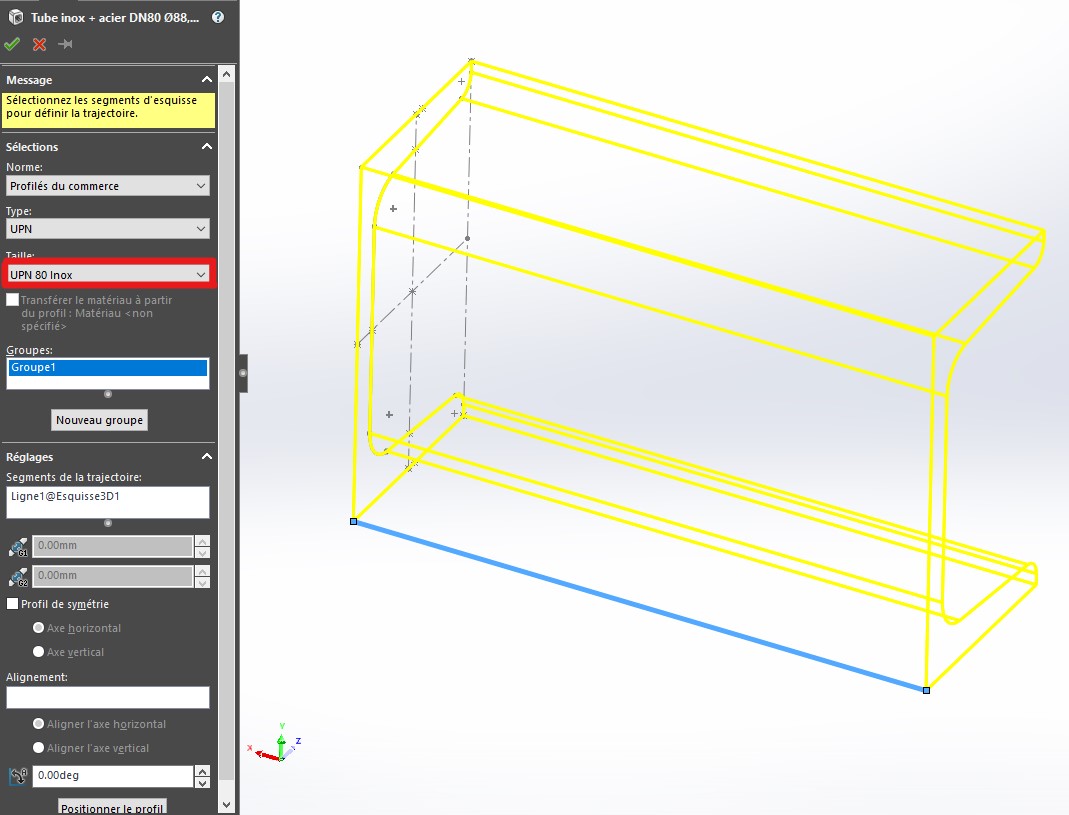
Hello It is perfectly possible to change the size of an iron but not to replace this iron. I attach a file that can be controlled directly by the mechanically welded function.
I thought I had been clear: the size of the profile is not controllable, but the dimensions of the profile are controllable: so it is still possible if you change the dimensions BUT NOT the sketch of the profile.
Warning: we end up with quite significant risks with the control by excel because the dimensions will be controlled by excel and not really by the choice of the section by editing the function. This is at least very disturbing for the user and there is a risk of entering dimensions that are non-compliant in the Excel table (unless you put a table giving all the dimensions of the different profiles: on a second sheet for example)
Hello; Have you tried it with DriveWorks (Xpress)? If it supports mechanically welded profiles, it should solve your problem... To be tested. Kind regards
Thank you for your proposal, indeed I hadn't considered it because I don't know the module at all. If anyone knows tutorials for my problem I'm interested. I found a few but it's about the first basics of use of DRIVEWORKS XPRESS... The subject of mechanically welded elements is not addressed.
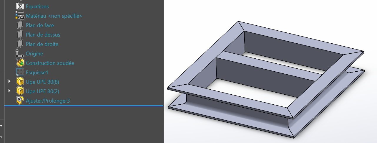
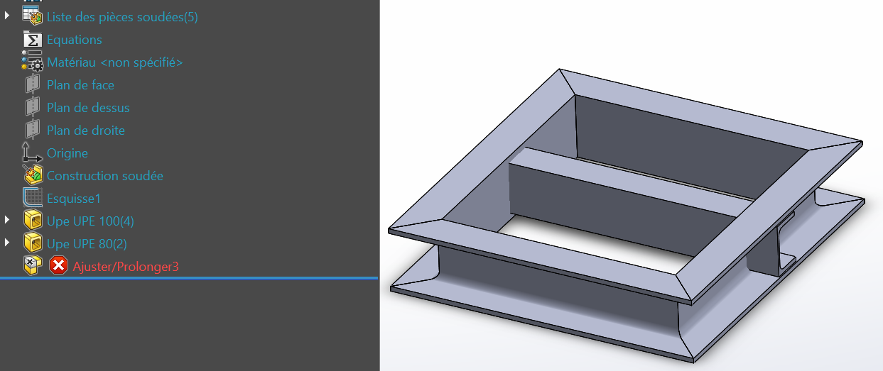
Hello in the event that you manage to control your mechanically welded assembly, I think that the Adjust/Extend functions will not follow because the reference faces will have changed. I tried a very simple part
Thank you for your answer! However, before getting to that point, I should already be able to manage my profile... For the rest I would manage with a removal of material if necessary
I'm still looking for a solution for my initial problem