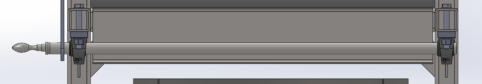
In reality, the chain is used to roll up a bag. The two 25/50 sprockets rotate an axle or a bag is attached to pull it, in itself there is no big resistance, the bag itself must weigh 2 kg and the material inside must weigh 5 kg.
And the distance between the two axles is 460mm.
And at the same time I would like to know if for the circlips you should undersize the inner diameter. For example, I have an axle that is 12 mm in diameter, should I take a circlip of 11.7 mm in diameter?
Just slide on the axle, otherwise you have to go through a groove on the axle, I don't have the standards in mind anymore but if your axle is 12mm the groove must be 10mm mini.
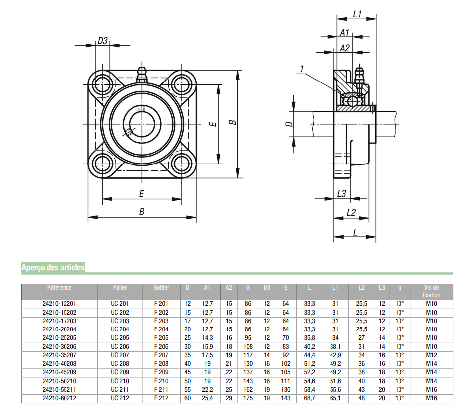
Hello For your crank, the bearing you chose simple is a 1-row ball bearing so it will bear that radial force. Since my company manufactures bearings, I would rather advise you To use a bearing with 2 ball track angular contact, which will allow you to have as much a radial as an axial resistance. After if you tell us the size of the crank axle and the bore where will be located the bearing, I will already be able to switch to a type of bearing suitable for this function and also know about the load that your bearing will eventually have to support
The crank shaft is 24 mm in diameter and the internal bore of the bearing is 25 mm in diameter and for the load I think it is only the mass of the chain and that of the crank, which must correspond to 50 N.
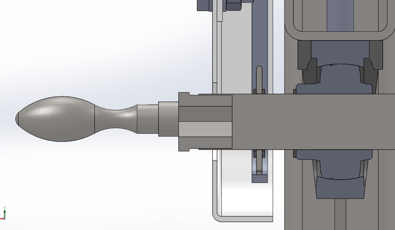
I added a widening to the crank so that it can be the same diameter as the bearing. It's up to you to tell me if it's suitable or not.
I'm not going to lie, bearings are not what I know best ^^'.
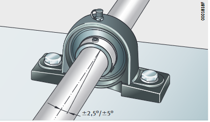
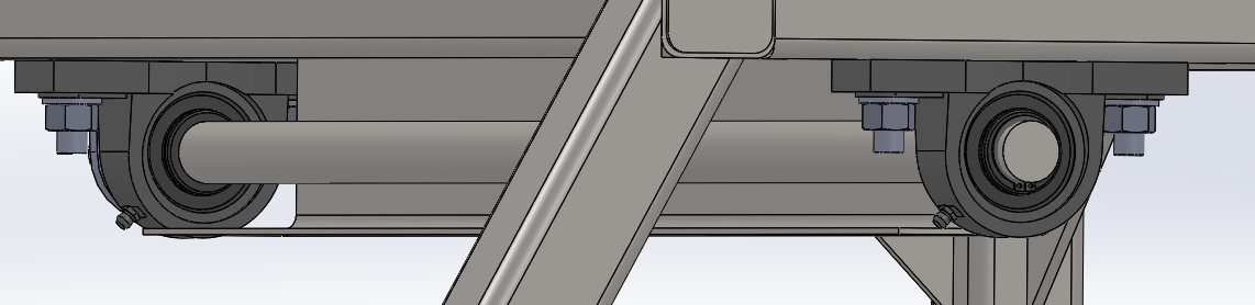
humph! The landing is sized to lift an elephant, isn't it? In addition I see a grease nipple which leads me to think that there is no bearing but a bronze or similar bearing. Although we only see a very small part of the system, who says chain says protective housing even and especially if the second hand of the operator takes care of the bag. The CHST or other well-intentioned person will not fail to make a remark to you.
For me, a bearing of this type alone is not mechanical, the bearing is oscillating like a ball joint to be self-aligning. So nothing prevents the axis from rotating slightly here supplier doc as an example: For me either 2 bearings or 2 bearings, bronze bearing but never a single bearing especially with a crank as a lever arm.
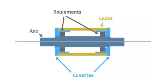
For me, put either a bearing on each side of the tube, or a bronze plastic ring or bearing, but in a quantity of 2 to have a longer guide and which prevents the axle from balluring. Just like a bicycle crankset, the assembly includes 2 bearings.
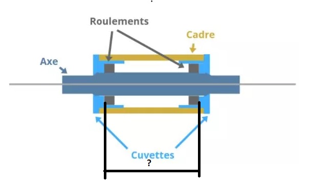
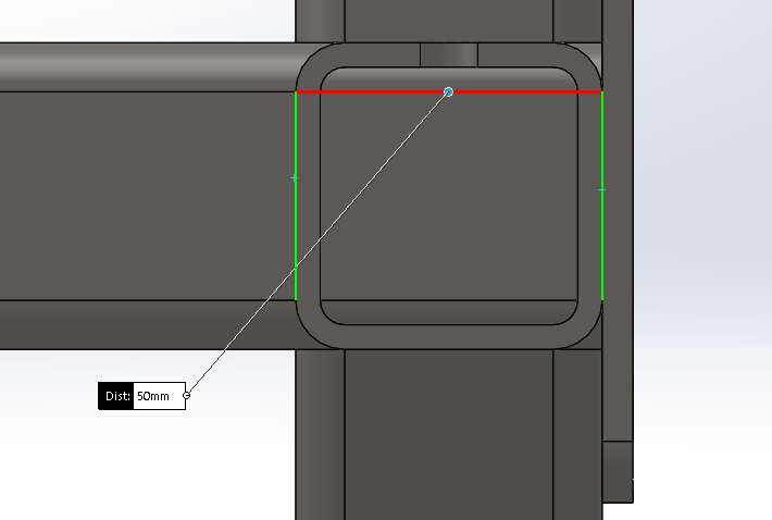
The problem is that I don't have enough space to put 2 levels as shown in the diagram below.
I have to be able to implement a single bearing where a roller to hold the axis, that's why I had a roller (maybe oversized it's true). I don't know if it's possible or useful to put only one roller/bearing.
Maybe with a shaft completely through your profile you can put a bearing on each side to prevent the shaft from pivoting. Ideally, you should also determine the loads in order to be able to size the shaft and the bearings associated with it. Once dimensioned, it will be much simpler to design the system.
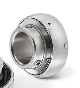
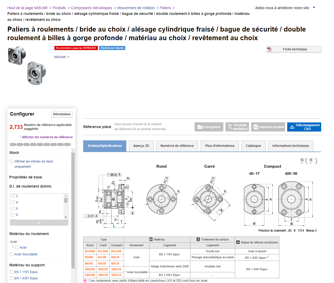
What I can advise you, so two 1-row bearings If there is a risk of dust: Choose with seals like this you can be sure that dust or other elements will not enter the bearing and it will allow you to avoid changing it
After that as I don't know the limit of the external diameter I just filtered on the bore and gaskets, I hope the filter will still be active
For the width you have to look according to the element where the bearing will be put do not take bearings with AIs wider than the AE preferably
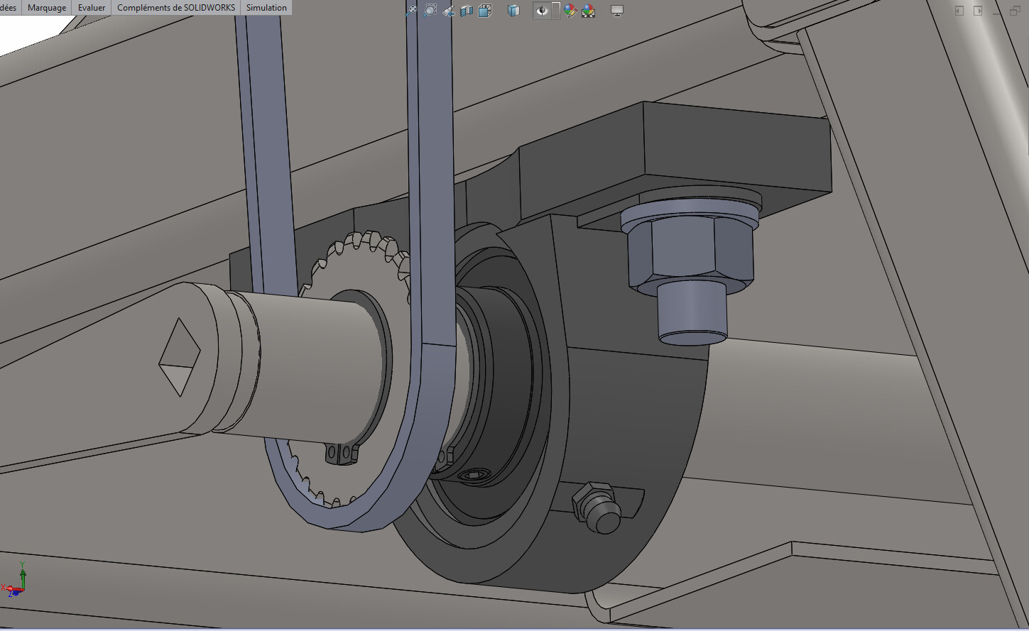
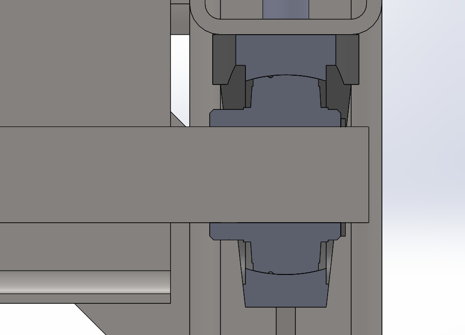
The sprockets that are fixed on the 25mm axle have a flat so that they cannot rotate around the axle and are blocked by circlips. I positioned two bearings with a 25mm diameter bore by putting circlips on them adjusted at the end to hold the axle.
The whole thing is oversized but I prefer it this way.
If you have any remarks or comments, don't hesitate to let me know about them.
For the bearing part, it seems much more mechanical to me. For the pine nut, the flat worries me a little. In general, to fix a pinion on a shaft, a key+ key groove is used And instead of the circlips, a BTR locking screw on the pinion shoulder (as on the bearing ring) seems more appropriate to me
I will add a (positive) shoulder on the shaft at the level of the second landing, you will gain two circlips... In addition to the groove/keyway drive offered by @sbadenis (What is the distance between the two bearings?.. No doubt you will need to provide grooves (if they do not exist on your bearing holders so that the two bearings are coaxial...)
 and also know about the load that your bearing will eventually have to support