Je n’ai jamais utilisé les configurations et dans le cas précis je ne sais même pas si c’est la bonne solution.
J’explique !
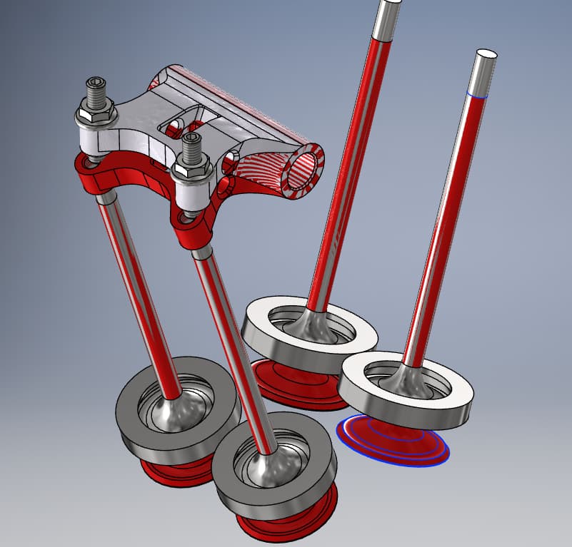
J’ai un grand assemblage qui comprend trois autres ASM.
C’est trois sous ASM sont strictement identiques et font 106 pièces chacun.
Celui du centre et le Sous ASM Master qui asservit les deux autres sous ASM.
Les deux sous ASM esclaves ont des pièces en moins mais pas en plus et pas de pièces différentes entre master et slaves
Le problème c’est que pour obtenir la nomenclature des esclaves je suis obligé de supprimer des pièces.
Mais quand je supprime des pièces esclaves cela les supprime dans le master bien que ce dernier n’ait pas le même nom.
Solution A je supprime dans l’arbre les pièces de l’esclave (sa met la grouille dans le master.
Solution B ( comme vous êtes hyper beaucoup sympa vous allez me l’indiquer).
Sachant que le proto est fini et qu’il faut que je fasse un nomenclature pour l’asm principal (ça c’est fastoche).
Mais il faut aussi que je fasse la nomenclature de l’esclave pour que mon sous traitant fasse les prix pour les deux modèles. Vu qu’il aura plus de 200 « ASM global » nous devons être précis.
Nota : Si je supprime seulement de l’affichage dans l’arbre cela est sans effet sur la nomenclature bien évidemment.
Je comprends qu’il s’agit donc de 3 instances du même sous-assemblage. Exact ?
J’avoue être un peu perdu… 2 variations du sous-ensemble ? L’assemblage de plus haut niveau se décline en plus de 200 variations ?
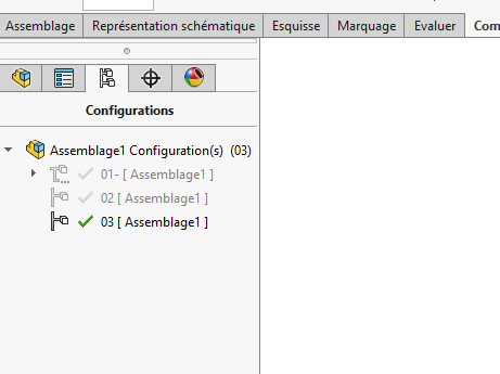
Les configurations peuvent être la solution.
Selon le nombre, utiliser une famille de pièce excel. Il y a également possibilité de piloter le changement de config de certains sous-ensembles selon la config d’un sous-ensembles particulier à partir d’équation défini dans l’assemblage de plus haut niveau…
Il faudrait plus d’éléments pour bien comprendre la structure de fichier et les différentes variations nécessaires et cette notion d’asservissement voulu entre les sous-ensemble… si possible.
Bon ce que je comprends:
3 sous assemblages issu du même assemblage, insérés dans des configurations différentes.
Donc oui les configurations te seront utile, mais les familles de pièce aussi (ce sont des configurations pilotées par une feuille excel). Je déconseille personnellement les états d’affichage pour ce genre de besoin (état caché ou pas), par contre elles peuvent être piloté appliquer une couleur.
Pour la configuration vous connaissez l’onglet nécessaire à la création. Après il y a des options qui faut bien lire pour ne pas être surpris.
Ensuite la suppression des pièces que vous ne souhaitez pas dans l’une ou l’autre configuration rien de plus simple.
Mais attention à bien être organisé, c’est vite le foutoir .
A la création de configuration des options apparaissent par ci par là, pour mieux comprendre les configurations je vous laisse déjà lire l’aide SolidWorks
Bonjour,
Si j’ai bien tout compris : un assemblage composer de 3 sous-assemblages de base identique mais avec une variation (des pièces en moins).
Ce que je ferai :
sous-assemblage en configuration MASTER : toutes les pièces présentes
sous-assemblage en configuration SLAVE : les pièces en trop en état supprimées
création de l’assemblage principale : 1 sous-assemblage MASTER + 2 sous-assemblages en configuration SLAVE.
Normalement cela fonctionne bien.
Je viens de comprendre mon erreur grâce à vous !
Résumé
Master est composé de « n » sous asm. Les pièces que je veux supprimer pour certains pieds sont aussi dans des sous ASM.
Evidemment si je supprime un objet dans un sous ASM comme il est commun à tous les pieds cela se répercute dans tous les pieds ce que je ne veux par pour le master.
Bref je suis comme un couillon donc la seule solution serait de repérer ses pièces une dizaine et les virer à la main dans la nomenclature.
C’est jouable car je n’ai que 3 nomenclatures en jeu pour l’usinage.
Une master, (un seul master)
Une pour les deux esclaves (identique pour les deux pieds)
Une pour les pieds neutres (identique pour les quatre pieds)
Après je fais le total dans un feuille excel sans se tromper comme disaient les anciens à l’atelier « c’est un peu gaulois ton truc »
Est-ce qu’il y a un autre moyen qui ne nécessite pas de faire grosse modifs. ou pour éviter la propagation ???
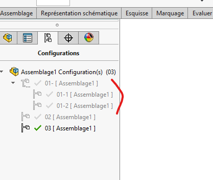
Si tu as un assemblage général A avec un sous assemblage B comportant un sous assemblage C, pour faire une config en C (C1 et C2) il faut également faire 2 config en B (B1 et B2).
Et Si sous assemblage D, E… même chose tu pars du sous assemblage le plus bas et tu modifies tout les assemblages en remontant jusqu’au point le plus haut.
@sbadenis , c’est exactement ce qu’il faut faire.
Mon exemple est donné pour 2 niveaux d’assemblage.
Plus on augmente le nombre de niveaux et plus il y a des configurations à gérer !
Il faut être TRES rigoureux sinon c’est TRES vite le bazar
Et pour compléter le chapitre ATTENTION, assure toi que le design de tes pièces est figé. Toute modif ultérieure créera des erreurs, dans la plupart des cas. SW étant très susceptible.
@Le_Bidule
Normalement si les pièces non pas de cause à effet entre elle (reference externe par exemple), et que les references sont cassées. Si non les mises à jour ce font bien ? enfin chez moi !
@Le_Bidule
Si vous fonctionnez avec la fonction mécano-soudée c’est normal.
Il me semble quand vous remplacez le fer par un autre, la fonction change les esquisses. Et malheureusement les surface ou arrêtes auxquelles sont accrochées les contraintes changent donc problème.
Si vous fonctionnez avec une esquisse il vaut mieux modifier celle-ci d’un UPE100 à UPE 120 en jouant sur les côtes. Dans ces cas-là pas de soucis.
Si vous créez un bloc c’est le même problème qu’avec la fonction mécano-soudée
Je travaille en squelette toutes mes pièces sont indépendantes pas de contrainte, pas de problème
Bon finalement après avoir compris grâce à vous où était mon PB.
Je choisi de gérer les pièces dans les nomenclatures des s/s ensembles (un sous ensemble = 1 master ou 1 esclave les neutres sont hors sujet.).
Evidemment la solution manuelle pour des « vraipros » comme vous cela va vous coller des frissons. (vu la météo en ce moment les frissons sont les bienvenus) .
Moi je ne fais que du « one shot » pas de série donc moins de rigueur que vous, c’est pour ça que je ne me suis jamais intéressé aux configurations.
Il y a quelque année de pratique, mais rassurer vous la plupart d’entre nous sommes passés par là (à mon époque pas de forum tuto comme aujourd’hui). Et je ne suispas un pro.
Pour répondre à cette information que je pense erroné :
Moi je ne fais que du « one shot » pas de série donc moins de rigueur que vous, c’est pour ça que je ne me suis jamais intéressé aux configurations.
Il ne faut penser comme cela, il n’y a pas de Oneshot, vous verrez à la longue toutes bidouilles vous pèteront à la Gueu… d’une façon ou d’une autre. A chaque fois que j’ai pris des raccourcis cela à mal fini .
Il faut se dire que petit, grande série, gros ou petit projet, il y aura toujours des modifications à apporter. Si vous construisez simplement (parfois simple ne veux pas dire facile et rapide) vous gagnerez du temps dans vos modifications ultérieurs, et il y en aura c’est sûr dans 99% des cas.
concernant les bibliothèques de profile mécanosoudées
pour eviter les erreurs de contraintes en ASM
le plus simple et d’avoir une bibliotheque de profil *.SLDLFP , avec 1 seule esquisse et toutes les tailles de profilé en tant que configuration de votre fichier model
si vous êtes à en refaire une complète, je vous encourage même à repartir de votre fichier de départ (par exemple des tubes carrés) pour en faire un autre fichiers (de tube rectangulaire par exemple). les faces ayant été généré avec la même esquisse ( trait par trait dans le mêmes ordre d’un fichier à l’autre) devrait normalement généré le même ID (identifiant qui permet à SW de retrouver ses petits) et donc la face N°00xxx sera la même sur votre profile après remplacement, un peu comme un remplacement de pièce dans l’asm qui ne pose aucun souci si vous aviez copier le nouvelle pièce en partant de l’ancienne sans modifier les faces qui sont contraintes
En théorie même esquisse de départ donc même face, mais en pratique pas toujours vraie loin de là.
Et pourtant c’est comme cela que nos bibliothèque de tube carré rond sont constitué (avec famille de pièce).
Si on reste sur la même section (tube carré par ex) pas trop de soucis, par contre si on passe en tube rectangulaire, les faces sont très souvent perdu (et contraintes par la même occasion).
Et pourtant le tube rectangulaire est bien issue du tube carré à la base…
J’ai eu le problème par le passé.
Dès que vous changez un trait de l’esquisse par un autre. C’est simple à résoudre quand on passe d’une section carrée à une rectangulaire. En partant de l’une des deux esquisses (carré par exemple) et que vous l’utilisez pour créer la section rectangulaire plus de problème. Sauf si vous changez les orientations.
En revanche, il est plus dur de conserver les bonnes entités d’esquisse quand on passe du carré à un HEB. La forcement on une chance sur x de ne pas attraper la bonne surface.