I've never used the configurations and in this case I don't even know if it's the right solution.
Let me explain! I have a large assembly that includes three other ASMs. These are three sub ASM are strictly identical and make 106 pieces each.
The one in the center and the Sub-ASM Master who enslaves the other two sub-ASM.
The two slave ASM have less parts but not more and no different parts between master and slaves
The problem is that in order to obtain the nomenclature of the slaves I am obliged to delete parts. But when I delete slave parts, it deletes them in the master, even though the master doesn't have the same name.
Solution A I delete the slave parts in the tree (it makes a mess in the master.
Solution B (as you are very nice, you will tell me). Knowing that the prototype is finished and that I have to make a nomenclature for the main asm (that's tedoche).
But I also have to make the nomenclature of the slave so that my subcontractor can make the prices for the two models. Since he will have more than 200 " global ASMs" we have to be precise. Note: If I only remove the display in the tree it has no effect on the nomenclature of course.
I understand that these are 3 instances of the same subassembly. Right?
I admit to being a little lost... 2 variations of the subset? The highest level blend comes in more than 200 variations?
Configurations can be the solution. Depending on the number, use a family of excel parts. There is also the possibility to control the change of config of certain subassemblies according to the config of a particular subassembly from equations defined in the highest level assembly...
We need more elements to fully understand the file structure and the different variations necessary and this notion of desired servo between the subsets... if possible.
Well what I understand: 3 sub-assemblies from the same assembly, inserted in different configurations. So yes the configurations will be useful to you, but so will the parts families (they are configurations driven by an excel sheet). I personally advise against display states for this kind of need (hidden state or not), but they can be controlled by applying a color.
For the configuration, you know the tab needed for creation. After that, there are options that you have to read carefully so as not to be surprised. Then, deleting the parts you don't want in either configuration, nothing could be simpler. But be careful to be well organized, it quickly becomes a mess.
When creating a configuration options appear here and there, to better understand the configurations I already let you read the SolidWorks help
Hello, If I understood everything correctly: an assembly composed of 3 sub-assemblies of identical base but with a variation (minus parts). What I will do:
sub-assembly in MASTER configuration: all parts present
Subassembly in SLAVE configuration: Excess parts in condition removed
Creation of the main assembly: 1 MASTER subassembly + 2 subassemblies in the SLAVE configuration. Normally it works well.
If you have a general assembly A with a sub-assembly B with a sub-assembly C, to make a configuration in C (C1 and C2) you also need to make 2 configurations in B (B1 and B2). And if under assembly D, E... Same thing you start from the lowest sub-assembly and you modify all the assemblies going up to the highest point.
@sbadenis , that's exactly what needs to be done. My example is given for 2 levels of assembly. The more you increase the number of levels, the more configurations there are to manage! You have to be VERY rigorous otherwise it's a VERY quick mess
And to complete the ATTENTION chapter, make sure that the design of your pieces is fixed. Any subsequent changes will create errors, in most cases. SW being very touchy.
@Le_Bidule Normally if the parts do not cause and effect between them (external reference for example), and the references are broken. If not, the updates are good? finally at home!
@Le_Bidule If you work with the mechanically welded function, it's normal.
It seems to me that when you replace the iron with another one, the function changes the sketches. And unfortunately the surfaces or edges to which the constraints are attached change so problem.
If you are working with a sketch, it is better to modify it from a UPE100 to UPE 120 by playing on the sides. In these cases, no worries. If you create a block it's the same problem as with the mechanically welded function
I work in skeleton, all my parts are independent, no constraints, no problem
It's been a few years of practice, but reassure you most of us have been there (in my time no tutorial forum like today). And I'm not a pro.
To answer this information that I think is wrong:
I only do "one shot" no series so less rigor than you, that's why I've never been interested in configurations.
You shouldn't think like that, there is no Oneshot, you'll see in the long run all the hacks will blow you up... one way or another. Every time I took shortcuts it ended badly.
You have to tell yourself that small, large series, big or small project, there will always be changes to be made. If you build simply (sometimes simple doesn't mean easy and fast) you will save time in your subsequent modifications, and there will be some for sure in 99% of cases.

 as the elders used to say in the workshop " it's a bit Gallic your thing "
 correctly)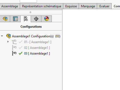
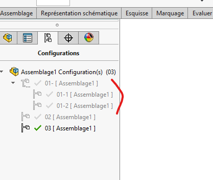


 badly.