Bolt Connectors

Hello

I would need some advice for the calculation of a tool (still under study). This is a tool intended for the handling of a pipe sleeve. It consists of 4 legs that are wedged under the upper bridle; These legs are connected in the lower part by spacers, the whole forming a kind of collar that is tightened on the cuff. To allow clamping, there is therefore a gap between the parts.
I would like to calculate the whole using bolt-type connectors; Problem: due to the design, the holes are slightly off-aligned, which the software does not accept for this type of connector.

Does anyone have a solution to my problem?
(FYI I'm a novice in calculus)
I am attaching a few screenshots to facilitate understanding.


3

Thank you in advance for your feedback.

Hello

Maybe with slotted holes on the nut side?

2 Likes

Hello
What I can advise you to facilitate the calculation and the simulation time is to consider the screws as parts; To do 2 solutions:

  • Represent an axis of cross-section equivalent to the screw instead of the screw
  • leave the screws during the simulation (without nut or washer)

You have to make sure that you have a contact between your elements for the simulation, so reduce the Ø of the holes for example so that they coincide with the Ø of the screw.

I don't know the load on your system, but to have a first order of magnitude, you can consider that the tightening torque of your screws is negligible at first, it can only be conservative...

And if not, there is a completely different way to do it, which is to isolate the study on a single part of your necklace, by dividing the load by the number of pieces that make up your necklace.

1 Like

Hello

Personally, I find it a bit strange to do this type of simulation.
Don't be surprised by the following and please take my remarks in a positive way if possible.

I'll summarize to see if I understood
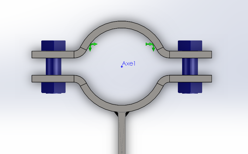
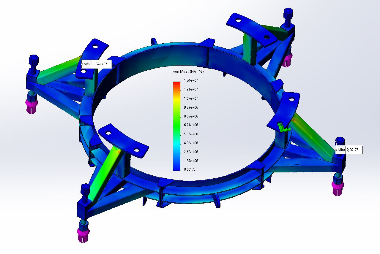
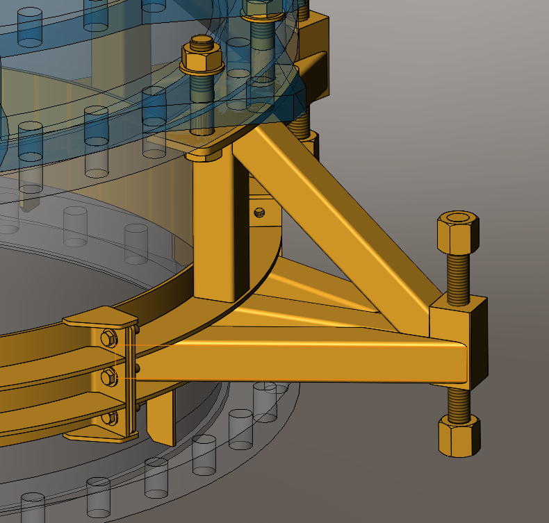
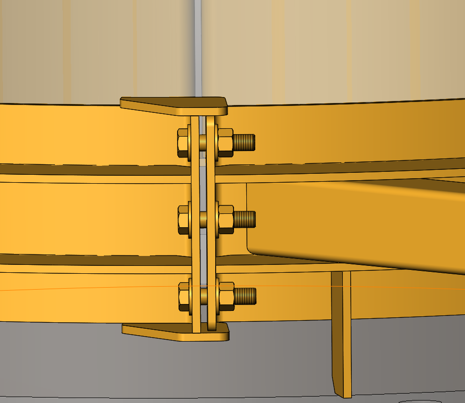
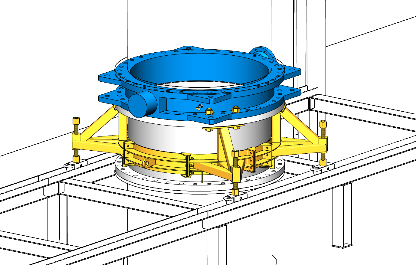
If we focus on the bottom collar, what would be interesting would be to see the deformation of the two vertical pieces that hold the three bolts and nuts.

The weight of the cuff or the handling conditions are unknown. (can you answer these 2 questions)
1°) is it a handling only for installation under the upper flange
2°) or does the tool remain in place and is subject to forces other than holding it in place (dynamic forces, for example during handling and assembly).

We can assume that it is just a matter of positioning before a more substantial assembly.
If my reasoning is correct (and not knowing the weight of the cuff, etc...) So even with a tightening of the bolts barely pressurized, it must be more than enough to hold the half clamps.

Conclusion for the simulation

No need for connector bolts which are really useful in more critical cases and where bolts play a more important role (AMHA).
As standard, the strength of the bolts is known and here we do not try to know their stress and resistance.

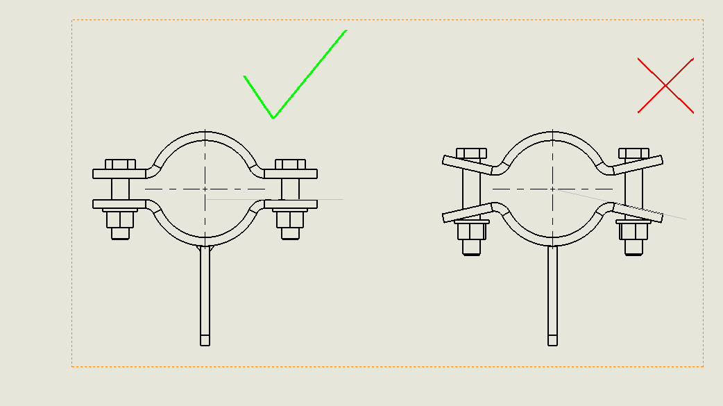
If you really want to do the simulation, you just have to do it on half a necklace by putting:

1°) a fixed part on the inner diameter of the collar (since the cuff is considered to be non-deformable given that it is not waterproof).
2°) make areas equal to the diameter of the washers (circle sketch + separation line function)
3°) apply a force on each area (force depends on the screw class 8.8, 10.9, 12.9 or even the screw manufacturers' charts)

Launch with a standard curvature-based fine mesh
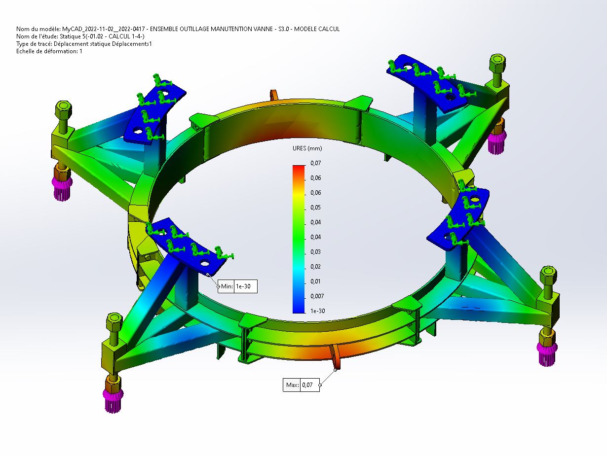
For the result, make the adjustment where the deformation is equal to the real (and not automatic which exaggerates the deformation by 1000%)

That's it while waiting for you to answer the questions since weight and possible dynamic stresses can influence the conditions of the study. This is a static study only.
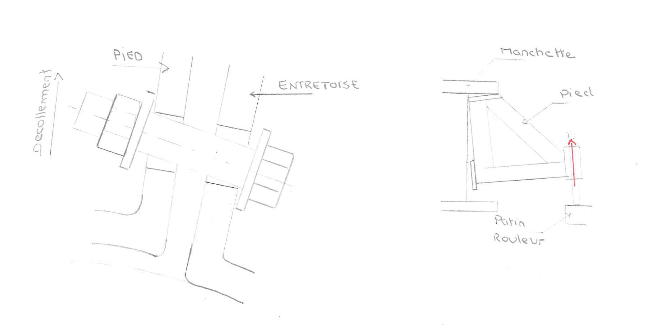
Zozotian prediction: the slight deformations, if there are any, will first be seen on the two outer bolts and more faintly see without deformation on the central nut screw

Kind regards

3 Likes

Hello

Thank you for your feedback. No worries about your remarks; on the contrary, it helps me.

To answer your questions about the cuff and handling conditions:

The tooling in question is intended to allow the installation of a valve (1600kg) + sleeve (860kg) assembly on an existing piping line (DN1400) instead of an existing assembly, similar but not identical.

To do this, a table in metal structure is installed around the pipe; this table has 2 U-shaped rails in which roller skates are placed.

We start by installing our new tools on the cuff. FYI, the valve and the sleeve are bolted together; We will therefore remove the 8 bolts we need to fix the tooling on the upper cuff flange.

The whole thing is then lifted and placed on the table, resting on the runners. The assembly is then slid on the table to the pipe for the assembly to be set in place.

This type of operation has already been carried out in the past. The aim of the study is to redesign a tool adapted to the new valve + sleeve assembly and which would be easier to handle and install. The old tooling consisted of 2 half-shell structures that were extremely heavy and difficult to handle.

It may be clearer with the image below:

As I can see, when the weight of the assembly rests on the 4 legs, they are attached under the upper flange of the cuff and will tend to come off the surface of the piping at the level of the " collar " area. My fear is that if you don't have a minimum of tightening at the level of the elements making up the clamp, the screws get a little " crabbed " and shear, especially since as you leave play between the elements (for tightening), you have no friction between the elements (see image below).

1 Like

Hello

The simple solution to do the calculation you want is to plug the holes on your parts and redo them in the assembly (so they will be aligned). If you have an angle problem on the support faces of your parts it will be more complicated: you will have to manage to have parallel nut support faces I think.

NB 1: if you don't really need to tighten the cuff, there's not necessarily much point in crushing it with your 4 segments. In this case you can leave a small diametrical game and have pieces that all touch each other cleanly without play. In terms of realization you could even pre-assemble the 4 pieces before making the holes of the pipe drilling circle → you are sure that they will be on a diameter and you can limit your bolt/hole sets.
NB2: Not taking into account the rigidity of the valve is very penalizing for the tooling. Taking it into account will allow you to be lighter (so you should have a more or less realistic modeling of the body, which it seems you have).

2 Likes

@froussel
I think that for the simulation, if you don't have all the yellow parts, you don't need to have the cuff. If the cuff flange is almost dimensionally dimensionally stable, it is sufficient to declare the contact areas as fixed areas in the settings.

To apply the forces we can put the forces from the bottom up on the simplified skates.

@stephane.yvart_1 Thank you for the images, it simplifies the understanding and the solution a lot

If you post all the yellow pieces, I can make you a simulation proposal. No need for the blue or grey room at first.
This will avoid being explained to you a lot of things that are not easily configurable in the simu.
Once the simu is done, it is easy to make the comments and show one of the possible methods chosen by us.

I'm a fan of the KISS method (keep it simple and stupid) which is an anti-shadocks :grinning: :blush: method :innocent:

2 Likes

Same opinion as zozo, keep it simple and parallel, there must not be this eccentricity, the support surfaces of parts assembled by bolts must remain parallel, it is often ignored (neglected the effect) for welded construction, anyway it will be the case with the distortion of the weld, otherwise considered using special washers.

1 Like

Hello (and thank you for your comment),

What I think I can do is create a "calculation" configuration of the 2 spacers by changing the angle of the end legs so that they are positioned parallel to the legs of the tooling legs. A priori like this I don't need to drill in the assembly.
On the other hand, I think I'll keep the game in the calculation.

My calculation relates to the tools only; So effectively the sleeve & valve assembly is considered rigid.

Yes absolutely, the valve and the sleeve are represented for the design but in my opinion no need to integrate them in my calculation. The difficulty is to find the most appropriate imposed trips.
In terms of loading I see 2 ways to do it:

  • A fixed lock under the nuts that come to rest on the pads + a remote loading down at the center of gravity of the valve-cuff assembly
  • Load each foot directly under the nut with 1/4 of the valve and cuff mass

Oh yes, if you can make me a simu proposal based on my parts, that would be great :slight_smile: ; we can compare our ways of doing things.

Below are the elements:
MyCAD.zip (2.5 KB)

@stephane.yvart I'm sticking to it this afternoon

1 Like

@stephane.yvart_1

Problem with your files.
You have to do a pack and go (menu ==> files ==> pack and go ==> select output in a zip file.

Kind regards

At the moment, this is what it looks like and it is unusable

Oh sorry :slight_smile:
Yes anyway given the size of the Zip there was clearly a problem...

It should be better with this one:
MyCAD.zip (9.8 MB)

I have moved forward in parallel on my side. I have created a modified version of the spacers for the calculation with parallel fixing lugs (cf. Lynkoa15's proposal) and I am working on 1/4 of the model with an imposed displacement of the " Symmetry " type...

Hello @stephane.yvart_1

When do you give us the new model with the modifications made so that we can do the simulation.

Kind regards

Hello @Zozo_mp ,

The files are in my previous message ("MyCAD.zip")

Hello @stephane.yvart_1

I have seen these files, but you have announced that you have modified them in the direction of simplification.

So which template you will finally use, the one at the beginning of the discussion or the one you would have modified simplified.

In the meantime, I allow myself a little off-topic remark
[HS ON]
If I read you correctly, the valve of (1600kg) is located much higher cuff (860kg)
Since your lift attachment is below the CG of the cuff, this means that the overall CG of the assembly will be very high.
So very unstable lifting and risk that the whole hut is very high (or even certain)

If I may be allowed an opinion, put at least three lifting points and especially resize the legs according to the sling because they are undersized AMHA and will not resist the slightest twist.

[HS /OFF]

Kind regards

Hello again,

I send you the modified files:
MyCAD_2022-11-02.zip (2.0 MB)
There are 3 configurations:

  • 1 entire model with no backlash between the necklace elements
  • 1 1/4 model with symmetries, no backlash
  • 1 1/4 model with symmetries, with a clearance equivalent to the CAD model but slightly modified to have parallel fixing lugs

As regards your remark on the CG, the lifting itself will not be done by means of the tools I design; The tooling is only intended for handling the assembly on the table.

Good evening @stephane.yvart_1

Here is the result of the simulation, I'll let you analyze the result.

I didn't use either the cuff or the valve.
I considered the crown of the cuff to be non-deformable since thicknesses greater than 40 mm are very strong
As a result, you have a tiny deformation (red area) due to the fact that the mechanically welded part does not rest on the cuff at this point.

I put fake steel bolts with batters since your first concern was about the connection zones between the mechanically welded elements

@Tous
Static study
Factor of safety greater than or equal to 4
Displacement

2 Likes

here is the ZIP

02-11-2022.zip Version (35.3 MB)

1 Like

Here is a video where:

The deformation is exaggerated by 10 times so that we can better see the slight deformations
In this new simulation I put the bolt holes fixed and no longer the fixed top side. As the crown stiffens the frame by using on the bolt holes, the rigidity of the cuff is deliberately eliminated.
This shows that the gap between the two ways of doing things does not call into question the solidity of the building.

I pushed grandma a little more into the nettles without it moving her in any way :face_with_hand_over_mouth:
Version of 03-11-2022 - deliberately exagérée.rar distortion (7.1 MB)

2 Likes