Hello
I would have liked to take advantage of it, but future version :(, on the other hand I see that you have fixed the upper faces, would it not be even more precise if you apply a contact without penetration + fixing at the bolt levels (virtual wall + anchoring)!?
Hello @Lynkoa15
From what I have understood contact without penetration is not suitable.
Non-penetrating contact is used when two parts are separated by e.g. several mm and when deforming the two parts will come into contact. From the moment the contact is made, the deformation stops since there is no possible penetration.
I fixed the upper sides because they are bolted on a crown that is more than 40 mm so non-deformable (see the images at the beginning of the post).
In the following post I only fixed the bolt holes and it doesn't change much.
What for! I put the pressure from bottom to top is that it allows you to see the deformations or even the blockages that can occur on the rails that are used to slide the frame + the cuff + the valve.
Why if the upper part is fixed it allows you to have the lower nuts free and therefore to see all the deformations on the X and Z plane
2 Likes
Hello @Zozo_mp (and hello everyone),
@Zozo_mp, thank you very much for taking the time to study my model ![]() .
.
For my part, I have difficulty getting something out of my calculation (big problems, especially with the "bolt" connectors)
To compare our methods:
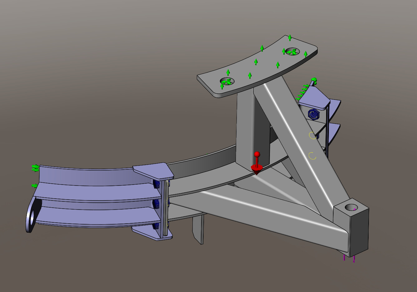
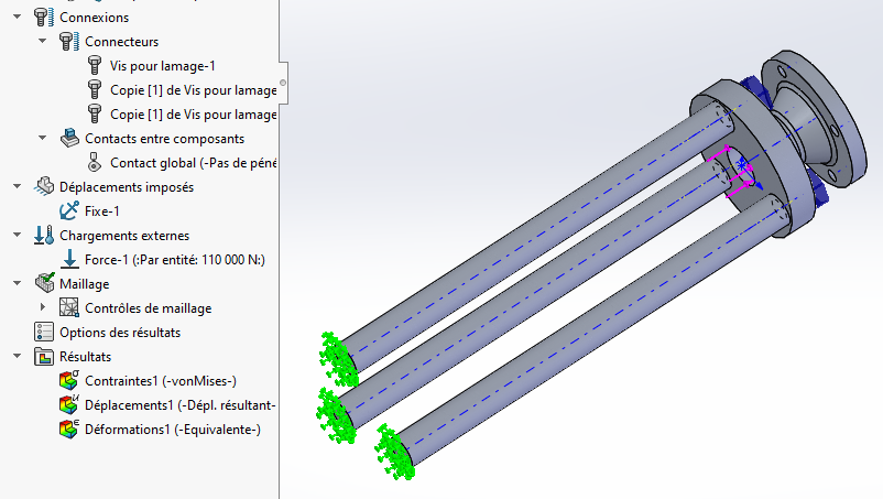
Parts: in order to simplify the problem, I am working on 1/4 of the model and I have excluded threaded rods and nuts. And I'm also in "all volume".
Connections: For my part, I have taken into account:
- Local "Contact" interaction between the legs of the collar area (to allow proximity without penetration)
- Bolt connectors with a preload of 60N.m (average value for a standard wrench tightening, without prestressing in short); and there is clearly a problem in my model since I have a constraint at 340MPa in this area, even when removing the loads... Your idea of "false bolts" seems interesting to me.
Imposed travel:
- Symmetry (since I'm working on 1/4 of the model)
- On the flats in the upper part: A flat support + pivot sliding into the holes (instead of the "fix")
- As for the contact between the tools and the sleeve tube, I don't know how to look at it; In a sense it is the tube that holds the tooling but for all that we cannot consider the whole as integral since the whole can detach from the tube...
Loads:
I take a safety factor of 2 at the start of the calculation:
- Gravity: 9.81*2 = 19.62 m/s²
- Loading: valve weight + sleeve 24600N / 4 supports * coeff 2 = 12300N (without taking into account the coeff on 6150; why 4000N for you?). For my part, an upward load, applied in the hole that normally accommodates the threaded rod.
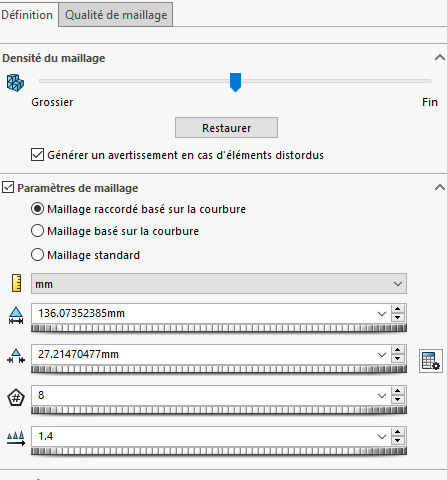
Mesh: based on curvature (is the connection more suitable?)
Don't hesitate if I'm not clear in my explanations ![]()
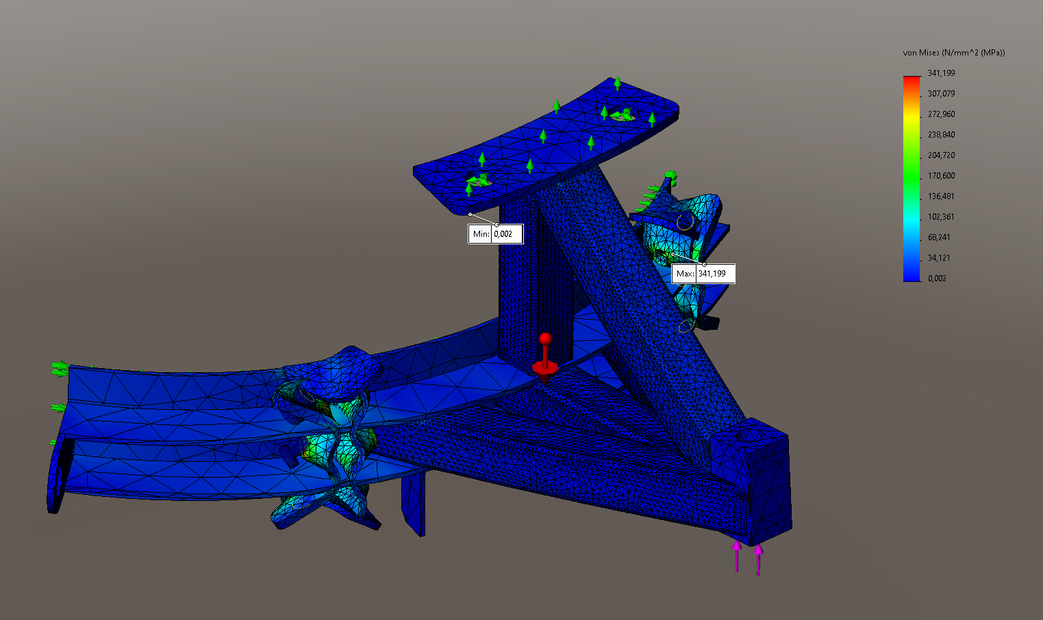
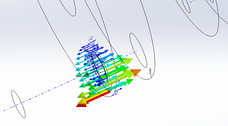
I'm attaching some screenshots of the loading and the constraint result
Hello again,
I have redesigned my calculation model following your feedback; In particular, I took up the idea of false bolts. It seems pretty consistent to me (73MPa in max stress on the tube diagonally under the upper plate).
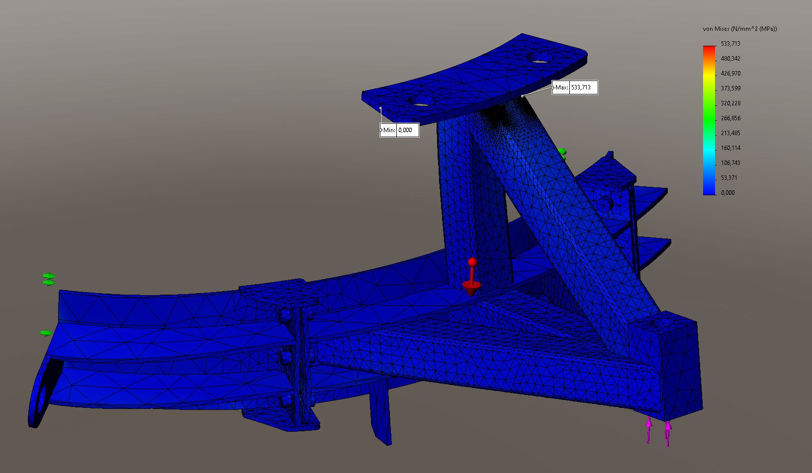
On the other hand, I have refined my calculation in the critical areas with mesh controls and I have no convergence of constraints; on the contrary, they soar (534MPa at the last iteration...). I roughly divided by 2 the maximum element size for each iteration.
I tried a calculation on the foot only and I have the same problem.
Attached are some screenshots (last result and mesh + tendency)
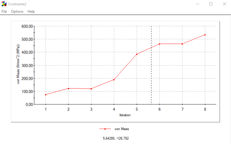
Anyone have an idea?
Thank you in advance for your feedback
I don't really know what to tell you, but in the friendliest way possible, here is what I can tell you from your latest images. Remarks made in the order of your last message.
You should know that, when you handle pieces of scrap metal in all directions for 55 years, you end up knowing how the parts will deform overall, especially on frames, it's simpler.
That's why I used a certain way of putting the fixed points and the loads.
We are greatly helped by the fact that your cuff is very large and very rigid. Rigid to such an extent that it is not needed for simulation since it can be replaced by the contact areas
Simulation allows us to better see stress concentrations and especially global interactions.
Your model is very simple and to the advantage
[NICE MODE ON]
-
Working on 1/4 of a model does not bring anything, since it takes less than three minutes to do the simulation on the entire model. In addition, if you look at the model or the video, you will see that there are distortions that come from or go to the other parts of the model. Working on 1/4 means that from the entire model we choose to analyze only a part of it.
-
You say that you are all in volume, but in the model half of the parts are declared "beam" or other. In theory, the mixed mode is not a problem, except that to see the results and in particular the stress concentrations, we see less well. You have to look at the status of each room and check that they are all in "Volume" mode.
-
I didn't use the non-penetration mode for the following reasons:
a) For there to be contact, the internal diameter of the frame would have to be able to decrease, which is impossible since the internal radius is less than 2mm.
(b) There should be no bolting on the crown of the cuff so that the parts can come close to each other. -
I thought I had told you that bolt connectors were a dead end. My statement is confirmed by the analysis which shows that the parts do not get close to each other on the one hand and the dummy bolts are almost not stressed in tension
a) It's to prove what I was saying that I put fake nut bolts on you and you can see in the Von Mises results that they are not solicited.
b) I put these bolts in, because I could see that there was something that was bothering you. The pencil drawings of your first step were based on a false premise for the reasons indicated below and below.
c) False bolts simplify the calculation since they are considered parts and the results on these parts are more visible on analysis. -
You write "On the covers in the upper part: A plane support + pivot sliding into the holes (instead of the "fixing"
No, because these parts are bolted to the crown maouss sturdy this piece is totally attached to the crown.
a) As I presented that it would be moderately acceptable to you, I made a last simulation in which I only put the bolt holes of the crown as fixed.
The result shows a barely visible difference compared to a fixed on the top cover. -
You say "I don't know how to look at it; In a sense, it is the tube that holds the tools, but for all that, we cannot consider the whole as solidary, since the whole can be detached from the tube."
a) The sleeve prevents the diameter of the frame from decreasing, because internal Ø = external Ø of the sleeve (2 mm clearance on a Ø of 1422 mm is nothing at all)
b) It cannot detach from the tube because the part that has the bracon (strut) does not deform significantly.
c) The other parts that contribute to the strapping cannot move since the nut bolts are not stressed in normal use. (C.f: 4.c above)
d) "Loading: valve weight + sleeve 24600N / 4 supports * coeff 2 = 12300N (without taking into account coeff on 6150; why 4000N for you?). »
The total weight is 2400 kg, rounding 24000N / 4 = 6000 N per foot. I didn't give you the right version, but even with 6000 N per foot you still have a CS of 5.7. -
For the safety factor I don't indicate it at the beginning and I look at the one calculated by SW a posteriori. It just changes the look of the result but nothing on the actual CS.
For your information, for heavy load handling, a CS of 2 is insufficient. Because your CS is calculated in static and in the event of the slightest impact or elongation of a chain or sling you can happily exceed a CS of 2.
Our colleagues will tell you what they use ( @stefbeno or @ObiWan) -
Last point:
The presentation of your results shows unrealistic distortions.
The stress plot must be set correctly, as the automatic mode is often at 1000 or higher.
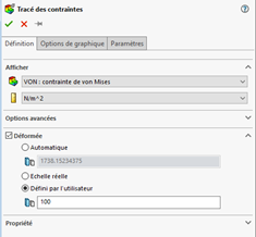
In the model I sent you back, it is at 100 otherwise you don't see any deformation, since the max displacements are less than a mm (even with 24,000 N of loads)
Kind regards
1 Like
With a very coarse mesh and without any fantasy, I have no concentration of constraints. I use a curvature-based mesh
Note that I still don't share your way of placing your constraints 'but hey ![]() )
)
1 Like
Unfortunately, I would not be of much help in this area as I am not very confronted with it.
From experience, I only know that in lifting (elevator) we are rather on a coef 10.
Moreover, when I have to size something, I prefer to avoid increasing the load: this avoids accumulations of " belt-straps " when someone reuses my piece and applies their own coef or has not seen that the coef has already been applied.
2 Likes
Hello
Questions about the presence of 4 " feet ", and about the " rigid " cuff...
The presence of 4 feet to place the structure on the rails raises the question of how the forces are distributed when installing the sleeve and the valve body.
The most unfavorable hypothesis assumes that one of the legs will not be in contact with the table, due to a poor adjustment of its height, or a geometric defect of the table rails during movement...
Formulated differently: what accumulation of " defects " can be admitted for the 4 feet to be in contact?
To carry out the simulation, the ground contacts of 3 of the 4 feet are modelled by " point" pipes , and the fourth is left free.
For the same reasons, the 3 by 4 feet ground support has an influence on the load distribution at the contacts between the cuff and the upper plates of the structure. To analyze it, it is sufficient to integrate a rough model of the sleeve and the valve body into the simulation. The load is then represented by the gravity on all the parts (2150 kg for the gate sleeve, 310 kg for the tooling).
The calculation time is only slightly penalized by these new parts, whose mesh can be quite coarse.
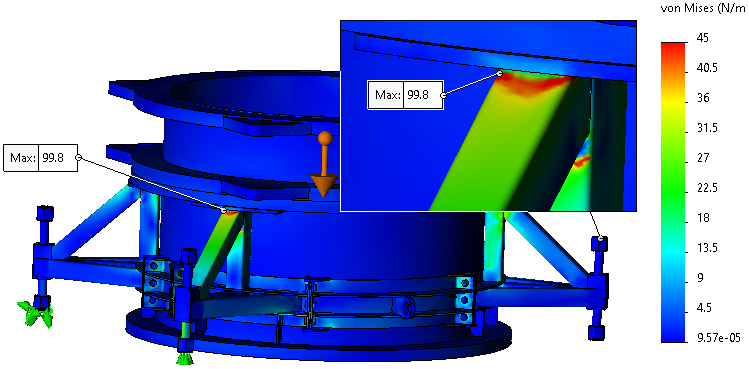
The results indicate a vertical displacement value of the detached foot of 1.05 mm.
This value is the maximum defect of the structure (table, tools, adjustment, etc.) to hope to have all 4 legs in contact. Be careful, the color code is unusual, because of negative movements: red = stationary, blue = maximum movement.
In this extreme case where one foot is detached, the load is borne almost equally by the two opposing feet in contact, i.e. 12 kN daN each.
The forces exerted by the cuff on the two plates associated with the loaded feet are approximately 16800 N, facing downwards. Conversely, the other two stages are stressed upwards, with forces of the order of 4900 N. It is the threaded elements that will be responsible for maintaining these contacts.
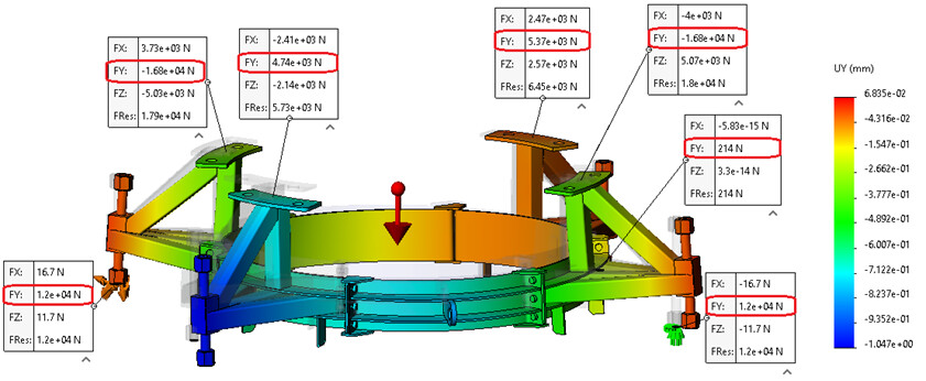
The stress remains within largely acceptable limits (cs > 5), except in areas of concentration with tormented geometry, at the connection of the upper plates and tubes.
Kind regards.
5 Likes
Hi @Zozo_mp ,
Non-penetrating contact works very well on bolted joints. This makes it possible to see the areas that are peeling off and the areas that remain in support thanks to the bolting prestress. You can also have stress increases in the bolts if their bending is significant.
As @Lynkoa15 said, managing a support surface on which the bolting would be linked will greatly increase the deformations of the assembly and surely see certain stresses rise.
2 Likes
Thank you @froussel
If you can bring additional information or an example it would be nice.
I was convinced that a bolt connector did not accept a space of several mm between two plates for example. I may have misunderstood or misrecorded how to use this connector during training. 
Kind regards
Here is an example of contact management and bolting: 3 columns bolted to a bearing. the bearing is subjected to a force tending to move the bearing apart from the columns. The columns are fixed to their bases.
This allows you to have the contact pressure between the bearing and the columns:
If the pre-treatment is too weak and/or the bearing too flexible, you notice that the support is only on the outside and that the columns are no longer in contact on the inside side.
Nb: be careful because the management of contacts makes the calculations very heavy because the calculation is iterative (so the calculation time can become very long).
2 Likes
Thank you @froussel very nice and well illustrated example
I understand what you did but in the case of @stephane.yvart_1 it seems to me that it cannot apply because of the large gap between the two turntables.
We don't get paid a lot but we have a lot of fun!
You're welcome @Zozo_mp
In the case of @stephane.yvart_1 , it would be sufficient to create a reference plane corresponding to the support face of the flange and to use 'anchor bolts' between the holes of its lugs and this surface considered to be rigid. It works well and it allows you to see the local deformation of the fixing lugs.
Otherwise the @m.blt solution works well too: you model the flanges and the pipe and at least you have everything (on the other hand if you manage the contacts and bolts it must start to take a little time in terms of calculation...).
The big plus of his complete modeling is indeed to consider the case with a bad support due to the hyperstatism of the 4 feet.
2 Likes
Thank you @froussel
But it is of course 
The right solution in this case is the anchor bolt which differs from the standard with nut.
gulp! I never use anchor bolts!
You're a very good guy!
Kind regards