Connectivity be => workshop

Hi everyone,

To deal with subcontracting and keep our production in-house, we absolutely have to reduce our study times.

As a result, I am currently working on a great improvement project: completely rethinking the workflow and the connection between our Design Office (BE) and our sheet metal workshop.

It's still at the reflection stage and the idea needs to mature, but here are the 3 main areas on which I would like to have your opinions:

  1. Switching to a global CAM

The idea would be to invest in a tool such as Trumpf TruTops Boost to program both our lasers and our bending machines.

The real plus: the operator would have the folding animation directly in front of his eyes, on the machine's screen.

  1. Say (almost) goodbye to 2D detail plans and move to PDM

The bent sheet metal parts would be managed directly by FAO.

We would only keep the classic drawings for the real exceptions (very specific machining, sharp geometric tolerances).

At the same time, we would set up a PDM to keep a clean history of each file and each document.

  1. Bringing 3D quality control directly to the workshop

Having the animation on the numerical control is great for the operator, but it's not enough to validate the quality of the part.

To permanently remove the paper plan, I would like to install terminals in the workshop with a 3D viewer (like eDrawings).

The operator could manipulate his part, take its control dimensions and make the direct link with the BE.

Before I dive into this, I would need your insights:

  • " Paperless " (or Model-Based Definition): Have any of you ever taken the plunge between design and sheet metal?

  • Software: What is your feedback on this type of flow (especially with TruTops Boost if some people use it)?

  • Pitfalls to avoid: What should you pay particular attention to when setting up? (Choice of computer equipment in the workshop, resistance to change of teams, management of tolerances...)

I'm super interested in all your advice, anecdotes or feedback to help me consolidate all this.

Thank you in advance for your help and have a good day!

Ho ba there, it's sure that subcontracting will no longer be able to compete with you... there is no longer a plan to consult them!

Joking aside, I'm always wary of this kind of project. And to be honest, I've never seen it in application.
There will already be a cost of implementation:

  • All workstations must be equipped with computers
  • All users must be trained in the use of computers + handling of software (clearly not the easiest point!)
  • the servers that are possibly well loaded (?)
  • User rights management

Then, what leaves me most perplexed is the management of the creation of the pieces. How are you going to be sure that the part is correctly made, without forgetting any function? You've probably done your calculations, but this puts you in front of a fairly high quality risk.
The plans still have this ease of pointing each function using dimensioning and therefore not having forgotten by the workshop

That's why, in general, in the companies where I heard about it, the design office ended up including the quotes directly in the 3D before export. And so I come back to the initial problem: where is the time saved for everyone?

1 Like

For machining parts without a plan I have already seen but with a color code for the reference faces and the types of holes adjusted or tapped, a minimum of dimensions in the 3D is possible

I don't know if it's done but there are very big companies, maybe it's worth visiting, like AMI https://www.toleriefine-metallerie.com/ you're a customer with them

Solution: contact Visiativ, there are a whole bunch of solutions, at all prices

Hello,

A few years ago I had to do a bit of the same project as you. The difference was that it was for 2.5-axis machining.
And as @Bob_2000 said, Visiativ helped us a lot to find the right software with the right partner (Eficad with the SwoodCam solution).

Document management was relatively simple:

  • customer plan and plan from the design office in PDF available in the ERP, so for everyone
  • machining plan of each part with visual, list of tools, and all the information that the operator needs generated in HTML by the programming software.
  • location of the HTML file managed in the ERP, the operator scans his OF and all the information arrives to him.

Between the implementation of the new programming software, the final formatting of the machining report in HTML, the deployment and the training of the operators in the new system, it took about 18 months!
To this was added the purchase of computer equipment, Dell all-in-one PC with a tactil screen (~1000€/piece at the time...).

Moving to 0 paper is feasible but you have to ask yourself the right questions. A mistake of choice at the beginning and it is the whole project that can be compromised!
Take the time to determine a specification, what the workshop needs, how does it need it, what are my input data, how to transmit them...

Also pay close attention to the compatibility between the different software! We had to do some tinkering because the production management software that pumped the information into the ERP (display of plans, deadlines, quantity...), found in fact unable to display HTML !! Coming myself, at the base, from industrial computing, I fell on the ass!

So I wish you a lot of courage for this project, I hope you won't be alone in carrying it. This was my case...

Hello,

We are not in 0 paper (but we don't do sheet metal work either).

On the other hand, we have EPDM + a shared directory for PDFs (the ' OLD school ' but computerized).

EPDM allows operators to access validated 2D/3D (2D/3D becomes inaccessible during modification by the design office: setting EPDM rights according to the user's status).

EPDM also allows operators to view 2D/3D via edrawing (which allows them to measure certain dimensions on files).

They retrieve the native Solidworks 3D BEs and put them in Mastercam to manage their machining (a bit like the counterpart of your Trumpf software).

If the Trumpf suite does not allow you to open native Solidworks, you can manage automatic export tasks upon approval of the plans (dxf, dxg, step...).

Solidworks manages MBD: there is a module for this (but you would have to talk to real MBD users to see if it could work for you).

If you haven't already done so, one of the first things to do in SW is to use your real bend loss coeffs (some forum users have experience with this), unless the Trumpf tool handles the unfolding (but it would be a shame to have a 3D SW file different from your real part).

Thank you for the time you have taken, for the loss at the crease yes we already have a coefficient in place but we enter it by hand each time

For the EPDM, is there a difference with the PDM?

Regarding the connectivity with the workshop, I find it super interesting.

Thank you for sharing!

Indeed, I am well aware that a mistake at the beginning will have a real impact later.

This is indeed why I am approaching forum to exchange with people in this field and who want to share their experiences and thank you for sharing them with me!

For the rest yes I know visiativ and their services well.

I think they are often a very good support but for some things we have to do our own research especially when we talk about such connectivity.

To give you some context, we're not going to remove plans 100%. The welding part will keep assembly plans with the positioning dimensions. On the other hand, for operators on laser cutting machines and press brakes, there will be no more physical plans: everything will be managed solely by CAM software.

My main fear:

This is change management. I'm afraid that the removal of drawings overnight will be badly perceived by operators and that they will lose their bearings, which would prevent them from doing their job properly.

The solution I am considering:

I think it would be better to go in stages. The idea would be to do a transition phase where we continue to provide some paper drawings, while deploying the new software programming in parallel. This would make it possible to see how the new system fits in and whether it meets their needs on the ground.

Have you ever experienced this type of transition in your workshops? How did you manage it to get the operators to join the project?

Hello,
If budget is controlled, why not and above all you have to make volume. A laser must rotate in 2/8 to achieve equilibrium???

However, advantages of subcontracting:
1/ No investment
2/ Guarantee of result (compliance with input data)
3/ Guaranteed lead time (and generally very responsive)
4/ Price set at the start / No surprises

1 Like

It's the management of the index that you have to ask yourself too. As much as on one plan, you manage to highlight the area to be reviewed (indicator table, dimension of another color, revision circle, etc.) As much as on the " paperless " version, it may be less " intuitive " (?)

For me the management of the index goes with the integration of a PDM, on which each modification is recorded, I find this even more reliable than a plan that can be poorly indexed.

Yes indeed subcontracting is operational overnight but precisely the goal is to update our production resources so that we don't have to abandon our production resources and our jobs

EPDM: PDM company so the expensive but complete version. It is now called SOLIDWORKS PDM Professional

SW also sells SOLIDWORKS PDM Standard: a limited version with many limitations (on workflow, software capabilities, etc.). Unless you work with 2-3 people with a very simple workflow I would advise you not to do it (but I admit that I don't know it well or have tested it)

A recap of the diffs:
https://www.goengineer.com/solidworks-pdm-standard-vs-professional-guide

1 Like

The clue will be on the coin. This is the case in some BE
Flat index
Coin Index

Hello

I have doubts about the quality only in the workshop. If you remove this control at each stage, you will have a fall in the workshop. On a sheet metal that is not too worked but on a machined part :thinking:

Hello,
I worked in the past with Solidworks + TopsWorks + TruTops (the old one, Boost didn't exist yet).
it worked quite well, and allowed you to use a single database (Trumpf, but customizable) for Solidworks (design) and TruTops (programming).
As a result, our Solidworks parts had the exact bend loss and bend radius, and we could export .geo files directly from Solidworks with metadata (material, thickness, punch/die combination). Folding was a breeze, the only things we needed to adjust were the bending stops and/or the bending sequence.

The machined parts will always have blueprints.

The time saved by an operator to carry out each drawing with the necessary unfolded folded sides is much greater than a fall by if by the

You weren't doing any drawings?
I didn't understand which software transmit the k-factor to solidworks can you detail

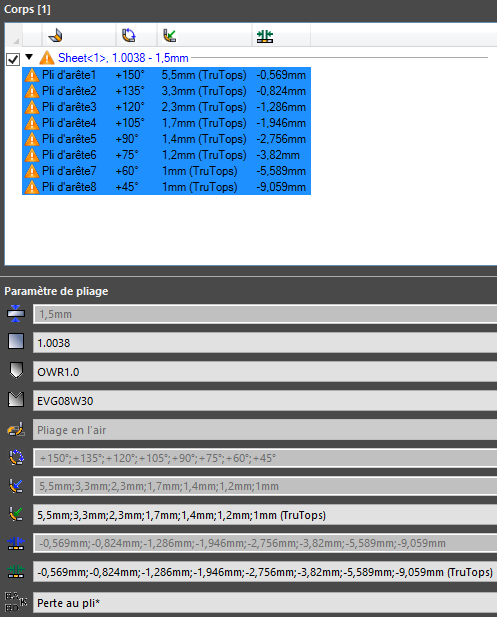
@AB3develop , we had a " TopsWorks " plugin that allowed us to read the values (loss at the fold, inner radius) of the Trumpf database, to automatically inject them into the 3D Solidworks file. And we could export a .geo file for the bending program with all the information (punch, die, material). This is what the TopsWorks menu looked like in Solidworks

For the plans, we only put the control dimensions for the production parts, and no plans were made for the prototypes, because we did both the design and the prototyping. And on top of that we were using the angle controller (ACB), so the parts were good 99% of the time, the times it was bad, it was because of human error like a bad stop.