Dans Solidworks simulation, pouvez-vous SVP, me précisez :
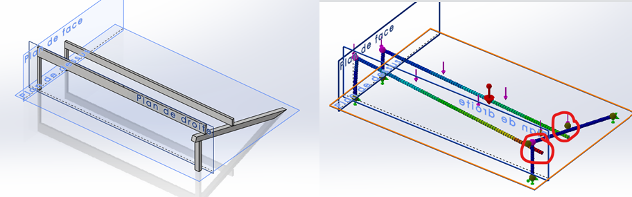
Comment faire une « connexion » entre des éléments poutres ? ; malgré le fait que le modèle 3D donne déjà les points de contact
Renseigner les propriétés mécaniques du bois, pour obtenir des résultats pertinents – Matériau orthotrope ? – et comment l’orienter en fonction de la longueur de la poutre
Enfin, comment forcer l’option « grand déplacement » sur un calcul « poutre »
Par défaut, les « connexions » entre poutres sont des encastrements à la jonction des éléments.
Pour obtenir un rotulage entre deux éléments, il faut définir au moins l’un d’entre eux comme une « Barre »; Les liaisons aux deux extrémités sont alors des rotules, et la barre n’est sollicitée qu’en traction/compression.
Pour modifier une poutre en barre : clic droit sur l’élément dans l’arbre de construction, option [Modifier la définition], case à cocher [Barre].
Ce même menu permet de modifier dans le détail les liaisons aux deux extrémités d’une poutre : pivot, glissière ou liaison à la carte.
Le bois, vaste question…
Si la structure est modélisée sous forme de poutres ou de barres, chaque élément est traité en unidimensionnel (RdM), et n’est soumis qu’à Traction/Compression, Flexion et Torsion.
Inutile dans ces conditions de définir un matériau orthotrope, les constantes d’élasticité (module d’Young, de Coulomb et coefficient de Poisson) sont à définir dans la seule direction de la poutre. Un matériau isotrope convient parfaitement.
Il est clair que la direction de la poutre doit coïncider avec la direction des fibres du bois.
L’orthotropie du bois est à réserver à des pièces réellement 3D, soumises à des sollicitations complexes.
Et la définition du matériau est une galère. Cf. directions du repère associé à un matériau orthotrope.
Sauf erreur de ma part l’option « grands déplacements » n’est pas proposée pour une structure uniquement composée de poutres ou barres. Elle ne s’applique que si un élément au moins est traité en volumique. Elle est généralement proposée en automatique par SW Simulation. Voir le lien proposé par @FRED78 pour forcer son utilisation.
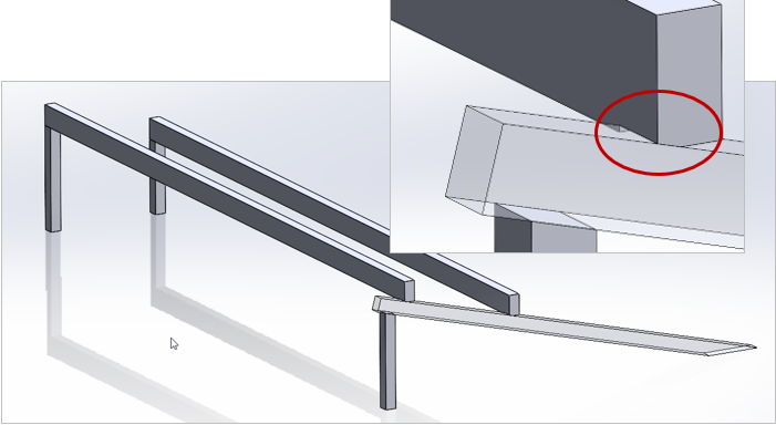
merci pour votre aide ; j’ai transformé des elements 3D en poutre, mais pour les liaisons contact sur arrete dans le modele 3D, le solveur de trouve pas de conditions limite, voir mon image ci-dessous
Bonjour,
Après quelques essais sur une structure similaire à la vôtre, j’en déduis que les contacts linéiques ne sont pas pris en compte entre poutres.
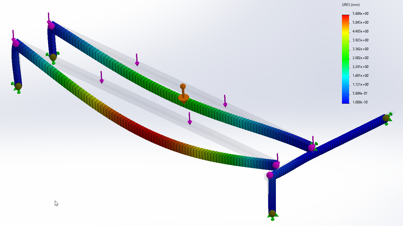
Pour contourner le problème, j’ai effectué un chanfrein localisé à l’extrémité de chaque poutre horizontale de façon à avoir un contact surfacique.
Si la surface est suffisamment grande, le contact est bien détecté, et le calcul se déroule normalement.
Merci pour ce retour
c 'est ce que j’avais essayé de faire sur le calcul en 3D, avant que je me rende compte qu’il soit préférable d’utiliser des elements poutres