Hello;
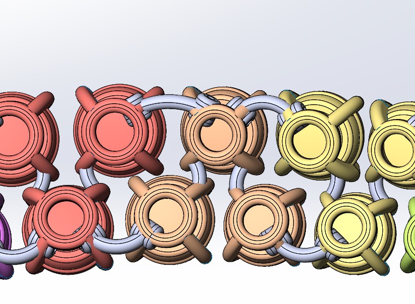
I make an assembly of derivative parts(A) that are connected with another derivative part(B).
My question is how can I alter my connector (B) so that it attaches to the same place of my parts (A) and on each side (see photo)
Thank you in advance.

Hello @flavie_michou
I wonder if your use of the derivative piece is relevant in this case.
As I understand your image, it is an agglomerate of several A&B pieces... So, why not make an assembly that allows you a lot more freedom as long as it is to manage your room B?
Thank you, indeed part B (meshing) does not need to have a derivative but it needs to be flexible according to the distances of parts A.
Please note that rooms A have different spaces and cannot be moved.
I don't know your professional background, or if you've ever used any other software. But the concept of rigid versus flexible is not the same for Solidworks as it is for Creo, for example.
In Solidworks:
If you have an assembly with moving components, rigid means that everything is relatively fixed (in place with each other) while flexible means that the parts can move... while respecting the previously defined constraints.
In Creo:
A part defined as flexible in an assembly can dynamically change shape. (and it's ultra practical!)
As of 2020 (I believe), Solidworks allows for dynamic shape change in some cases, using contextual references in top-down assembly design.
For example with springs: it is created from a twisted swept surface where the length is controlled using a contextual reference. This means that with each reconstruction, the spring deforms as it should.
If you had two plates and a rod between them with a spring (a shock absorber in short!), the scan path could be defined using a line between the two plates. So, whenever the distance of the plate changes, the total length changes.
This is nice, but seems to work for a single part in the assembly and does not seem to be able to be taken into account for several parts with several lengths.
Flexible Component Addition Example - 2023 - SOLIDWORKS Help
So, in your specific case, it seems to be wiser to make different configurations of room B to the right dimensions and to call the right configuration in the right place
Hello,
In SolidWorks it's the same! And the example you give with the spring is a good example and it works for all instances of a component.
There is indeed the notion of assembly AND flexible part in SolidWorks.
→ multiple instances of the same spring in an assembly, if defined as a flexible component, can each deform independently depending on the context of the assembly.
To return to the request for @flavie_michou :
Could you please be a little clearer? We can guess which is room A, room B... but we don't know if you are working in an assembly file (the notion of derivative having been mentioned, it can be doubtful), and for my part I am still trying to understand how the components should be linked together.
Can the files and a schematic diagram be shared?
I realized in my explanation that I got lost!
As far as I know: in Creo I can change any dimension to " flexible " according to your needs. Whereas in Solidworks it depends on previously chosen/declared constraints
Thank you very much for the info, on the other hand I have the impression that the springs can only be controlled by axles, except in my case the meshes are curved
Yes, I'm working on an assembly. Piece B is made up of 3 charnons on each side, the ends of which will be part of the A pieces
I think you could achieve the desired result by building a first connector in the context of assembly.
It's going to be very difficult to explain the method in writing, which is why I was asking for CAD file sharing, but let's try anyway:
- Build your connector based on reference geometry itself built from elements of the assembly context (A-part geometry)
Used path length dimensioning to allow geometry to twist appropriately
Insert a new instance of the connector and set it as a flex part. You will be prompted to replace the connector's external references.
thank you very much, I just created a test file hoping that it can be simpler (test A is simply a cylinder that I can't send because it's limited to two parts ![]() )
)
test A B.SLDASM (700.5 KB)
B.SLDPRT test (905.8 KB)
??
Without the complete assembly, it is difficult to understand how the parts relate to each other...
Does the assembly below exhibit the desired behavior?

Part2.SLDPRT (128.6 KB)
Assem1.SLDASM (199.8 KB)
Oh yes, that's great! Can you explain to me how you did it? Thank you so much ![]()
-
the cylinders and the Assem1 assembly are made first.
The cylinder has the elements necessary for its positioning in the assembly → look at the sketch that was used for the extrusion, in addition to the circle, I have planned the construction lines that extend beyond the circle. The end points of the construction lines outside the circle are the references of the coincidence stresses in the assembly.
It also includes reference plans that will be used in the construction of the Part2 part. -
The Part2 part is built in the context of assembly.
I'll let you study its construction knowing that the " -> " prefix in the construction tree indicates that the function/sketch references an external element. -
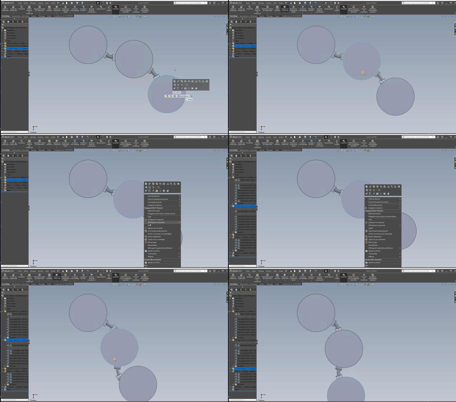
The last step is to convert the part to flexible (right-click on the component in the tree, then click on Make Part Flexible

You will then be prompted to redefine the referenced external elements according to the context.
This will be done for all instances of the component you put in the assembly.
CAUTION: Making a part or subassembly flexible affects performance.
Hoping I was able to help you... Good luck and good luck!
If this is ok for you, please close the topic by selecting the most relevant answer.
Hello Silver_Surfer, sorry for the late reply, I unfortunately don't find how to do the flexible part function. ( it works when I add a part in your assembly but not in mine ! On the other hand, the idea is great, it could be regularly useful!
What part are you trying to insert into your assembly?
Can you provide screenshots?
Hello
With a right click on the component and icon " make flexible "/" make rigid ".

" Making flexible " is a status, more than a function.
Not necessarily. It all depends on the version of your file and the " helpers ". A photo as an add-on is always a good idea.
What version is your file in?