I am faced with a problem of " propagation " of part stresses through several assemblies and I do not understand what is blocking.
For context, I've been self-taught for 9/10 months (and it's starting to be a problem) under Solidworks after 15 years under Creo. This sometimes plays tricks on me in the design intention, which is not always transposable to SW.
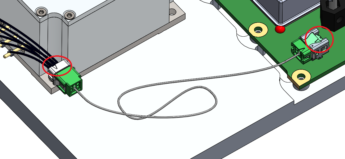
My problem is to represent a cable that connects 2 connectors in red:
My 1st attempt was to create a " cable " sub-assembly with the green connectors whose 1st shaft connector is totally constrained, then to assemble this S/E " Cable " in my head assembly. By wanting to position the connectors by constraints at the 2 ends, SW constrains the 1st connector but impossible to move the second, I have an error message asking me to break links or to constrain it. What for? Did I miss something? This 2nd connector was not constrained anywhere...
My 2nd attempt was to assemble the 2 connectors where they need to be in the head assembly and then to create an S/E (function in the context menu). It worked physically but all the constraints in place blew up! I left it at that, but the situation is not sustainable.
What do I do wrong in SW to not benefit from this flexibility of constraints regardless of the part, regardless of the level of assembly?
In what I understand and reasoning solidworks you have at least three parts concerned regardless of the ASM you do.
1st hypothesis you have five rooms a) The grey box on the left b) the green electronic turntable c) the green connector on the left d the cable e) the green connector on the right.
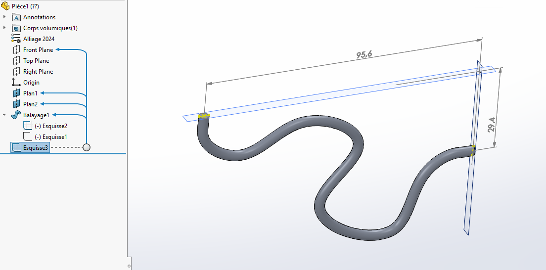
Whatever way you go about it, you have to consider your cable as if it were a 4 mm piece of round, made of steel, so completely rigid (like a wire or piano wire). After each connection is made by a plan. Once your cable is made, you have to have the sides that fit well on the female part. This means that you need to know the 3D dimensions on the connectors that are attached to the turntables. The cable automatically adjusts by changing the dimensions as shown on the attached drawing.
Note that we have a Master Es-cable (Hello @DoubleL) and if he goes through this he will give you a better construction tip especially if you work on 3 planes instead of two as in my example made in a hurry.
Be careful if you have several ASMs with the same cable, you need to find a naming rule for each global ASM.
Thanks for the explanation and the link to the help, I'll go and look at it. The notion of " flexability of the parts " seems very different between Creo and SW.
I don't really understand what is blocking you. Personally I work like this, it works every time (See attachment) squelette.zip (5.2 MB)
I work with a skeleton (that I take out of the closet ), I define it at the beginning of my project or not, and I insert it in all my assemblies. This avoids conflicts of constraint. The constraints are only at the level of the sub-assemblies. Much simpler to manage (especially when there is no design or method intention). In the head assembly, all the parts are blocked origin to origin, no ambiguity. Be careful in your assemblies of orientation constraints (parallelism), which can be confused with coincidences for example, and create over-constraints not always at the time you make them, but when you reopen them.
Hello For the part, I have several ways to do it: If you can afford it, it's to create a single part with the 2 green connectors inserted in the body of the part and to make your cable directly in 3D sketch, it's the fastest technique I use for hydraulic hoses.
Add a new part and fix its origin in the assembly.
make edge recoveries, in independent 3D sketches to position your connectors (in my case I get a circular edge from the starts of my layouts) (I then make a circular surface to be able to easily invert the normal 180° if necessary)
to simplify the readability I create a 3rd 3D sketch which will only be used for the trajectory of the cable)
I add my imported parts and I reposition them on my geometry (be careful to prefer a straight part at the beginning of the 3D trajectory of the cable otherwise sometimes you will not be able to make the concentricity)
To make a 2nd cable you just have to copy it and replace the extraction edges with new ones and the cable rebuilds itself.
2nd possibility, go through an additional row and break down (ASM of the equipped cable including 2 green end caps and an independent cable file. -do more or less the same thing:
position your fixed ASM (and make it flexible) to avoid untimely recalculations
add your components and position them by constraint from the upper ASM
Add your fixed piece (cable) and retrieve the edges to create it in position relative to your green connectors.
In case of duplication of a new cable, be careful to copy the ASM and share it as new components to avoid external reference crossings. so the easiest way is Pack&Go
Personally I don't really like this 2nd because in case of renaming we sometimes keep links and it's more cumbersome to manage, but we keep the decomposition of the nomenclature ranks, if it's important.
If it's not very clear, I might make a video on my youtube channel @TMa3D if you want!