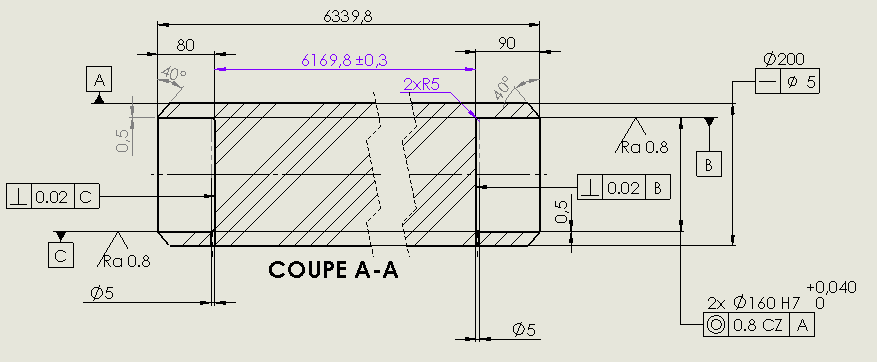
I have to dimension a very very long axis (more than 6m). At the 2 ends of this axis, parts are interlocked - welded.
A straightness is requested by the customer on the axle (5 mm) but above all it is necessary that on the final assembly (with the 2 interlocking end parts - welded) we end up with the 2 end pieces well aligned (the axle itself is not functional: it just ensures the mechanical connection between the 2 end parts).
The 2 interlocks being proportionally small (80 and 90mm) and the part being naturally not very rigid given its very long length, I wonder how to specify that the 2 small axes are well aligned with each other and parallel to the middle axis of the part.
Hello You have to take into account that it is not physically controllable so dimensioning this alignment should not be done at the level of your axis but at the level of the parts receiving the end pieces. The laser tracker is ideal for this. Your axis being flexible, given the length, it will align itself. Another thing, you can ask your client for a derogation to lengthen the interlocking. And for the dimensioning you can limit the geometric tolerance to a certain length (interlocking + ...). Sees eventually with the machinist and what his lathe can best achieve in precision, he will certainly put the axis between points.
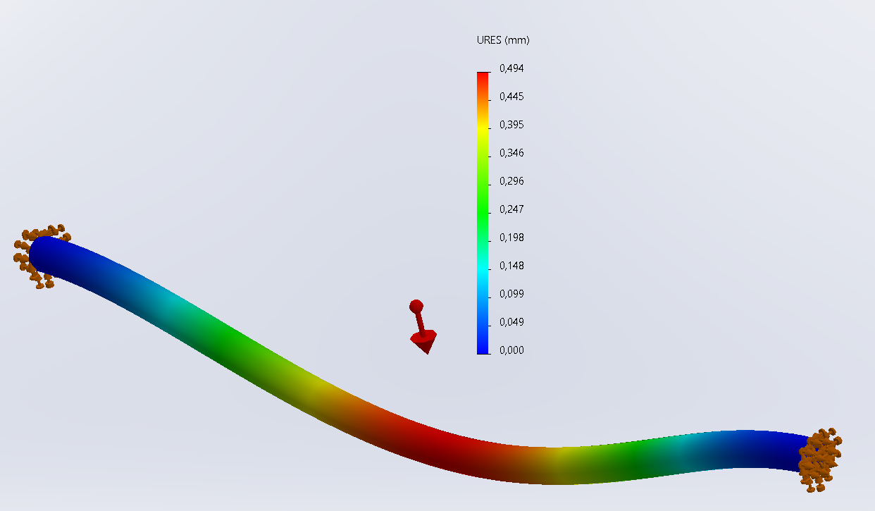
What is it made of? A simulation on SW with just gravity as an external force can give an indication of bending.
Yes, why not, but let's not forget that we shouldn't rate something that is not feasible or not justified. I quickly did the simulation with just gravity (self-weight) in C45 and well I'm surprised by the result since the result in deformation would be 0.494mm.
The manufacturing range is fixed (we are not going to bring in the 7m long welded part to mill the 2 end pieces). So it will be a mechanical realization of the 3 parts and then final welding. At the level of the sockets, going from 90 mm to 160 or 200 should not change much in terms of overall quality of alignment (if the 2 end machinings are carried out in relation to the first meter of round of each end, it will still not end up well aligned overall between the 2 sides).
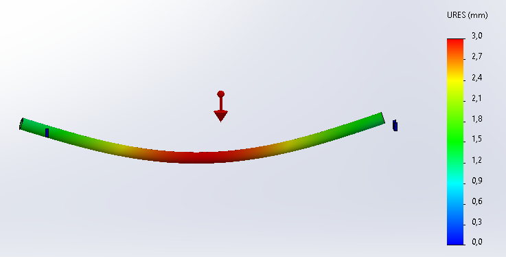
Your simulation is with 2 recesses. If you have 2 single supports at the ends you get 3 mm of arrow in the middle:
Suffice to say that with such an arrow the 2 interlocks are no longer aligned at all.
The final flexibility after assembly is not my problem (the design is existing and works well).
The concern is to dimension the part so that the 2 centers are concurrent (regardless of the gravity).
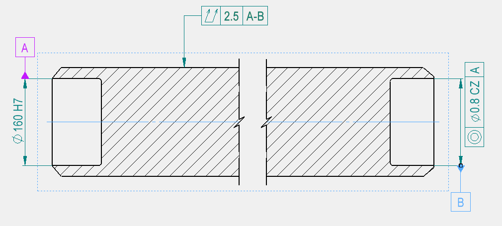
The dimension of @coin37coin is ultimately what I need but it feels quite weird to dimension a coaxiality (let's say 0.8 or 1 mm between the 2 ends) when the part is so flexible given its length. The fact that the reference surface is 70x smaller than the room also seems problematic to me.
It's not the most intuitive... but in fact precisely! It goes pretty well in the direction of your two words: the central axis is " only " used to connect your two centrings. Borderline, if he wasn't there, it would be the same (in a hypothetical world without the need for physical connections) So, you dimension your centering in relation to the other centering
@Silver_Surfer , your beat won't make your piece more difficult to make and prone to scrap? NB: Actually, thinking about it, since you have more concentricity compared to the central axis, it should improve ... but not easy to achieve in machining! You start with your centers and then grind your main axis
Won't your beat make your piece more difficult to make and prone to scrap?
→Well, yes! That is the problem. But according to the information communicated, it is the 2 end housings that are functional. The beat will implicitly limit the straightness and ensure the parallelism of the axes. It meets the need but really not easy to make given the length...
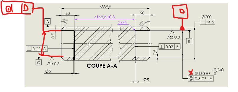
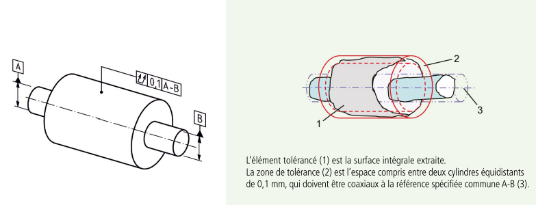
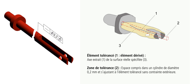
The double runout or straightness with an ø in the tolerances is functionally the same on an axis like this. The nuance is that the double flap defines its tolerance zone between 2 theoretical cylinders around the geometry of the part:
As the outside of the room is not functional at all, the straightness is more in line with my needs.
NB: images extracted from the ISO Specifications GPS Specifications memento published by Cetim.It's very well done and very clear. To be downloaded for Cetim contributors (logically all your companies should be)
It is a mechanical structure support axis that is articulated at the 2 ends. The add-on parts are the hubs for the hinge pins. As the part is subjected to buckling, it must all be well aligned (plus the fact that our customer has high requirements).
As indicated by @Le_Bidule, " we must not rate something that is not (...) not justified." As the messages go by, it is clear that it is safety with regard to buckling that justifies this listing. Hence some elements in the attached pdf, which do not propose a solution, but give a direction to the reflection. One last remark: the mass of the bar is about 1500 kg, and the critical load of Euler at buckling is of the order of 430 tons (if my Excel calculation is not rotten). We're not in watchmaking...