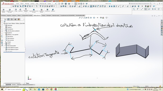
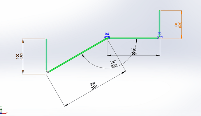
Hello everyone, I would like to check all my dimensions before unfolding in a sheet metal part document, to see if it corresponds to my external dimensions that I want. As on this sheet metal there are folds close and open, its complicated choses.je you a screenshot for more understanding. Thank you for your answers.
Marco
Hello
simply double-click on the " Bent1 Base Plate" function and the dimensions of your sketch will appear on the screen.
marco42marc. SLDPRT (66.2 KB)
In the drawing, you need to select the two desired lines and then click on "points" in "sketch". You then have a point to select to show your dimension
Another technique is to sketch on a side face and then convert the entities. Then you place your dimensions with the context menu (see images and use in particular the intersection search, very useful).
Also available in MEPs
You will then have the dimension of your piece and not that of the sketch that allowed you to make your piece
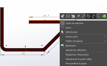
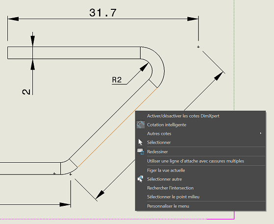
For me I rate like this:
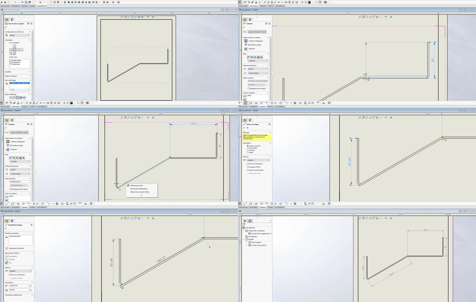
For the intersection point right-click and select the intersection. (for obtuse angle)
For the tangency shift + click on the rounding (=tangent, for acute angle)
And obligation to draw a perpendicular to have a dimension //.
Otherwise different odds (here 196.29 instead of 196.27 but on high thickness the variation is sometimes important)
It's beautiful with a video!
And what do you go through to save your GIF?
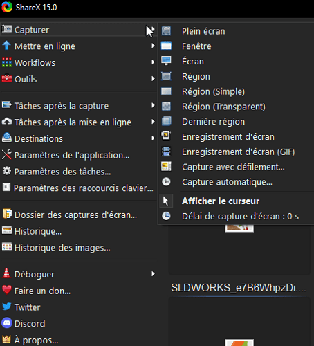
ShareX @coin37coin because opensource, easy to use and very complete for screen capture with addition of text, frame, arrow... Or screenshot, gif, video... And even putting the screenshot online if necessary.
