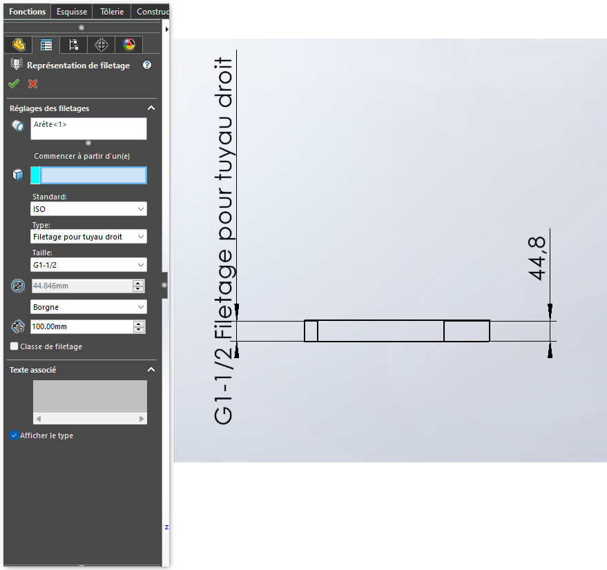
I am having a problem on the dimensions of thread representation. On an old piece, I find the left rib on my catch. I would have liked to remove the text after the coast, so I tried to uncheck " show type " in the 3D function. My problem is that as soon as I do that, and on a new part too, it's no longer the diameter in inches but the primary value that is displayed (right side on my screenshot). I notice that on the representations I create, I don't have the " insert symbol " function by right-clicking on the said representation.
How can we still find the left rib, possibly without the text " thread for straight pipe"?
Thank you in advance and sorry if this has already been discussed, I haven't found...
Hello krenard; Well come to the forum hoping that you find the solution here. For my part, all the texts come from 3D, so you can also manually insert by inserting a thread and choosing the right one, as you did on your screenshot. For the moment I can take a screenshot for you because my pc is being processed. But I'm sure someone has the right solution here. Good luck. @+. AR.
I don't have this behavior on the drawings. It only displays the size of the thread without the notion of thread type by laying down " display type ". Which version of SW?
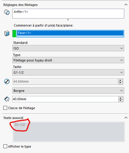
When I uncheck the " display type " box, it effectively removes the type of thread but also the format and unit of the dimension: " G1-1/2 " turns into " 44.8 " and that's not what I want. By the way, when I check the box, it leaves me with the " 44.8 " dimension without the type of thread so it's really my parameters that must not correspond to that of the creator of the part.
On the 3D it only displays the actual diameter for the function as far as I know. It is only in the map that it displays the right information (visible in the associated text field). I don't think there are any specificities related to the configuration of the workstation but good to see maybe on the side of the file that manages the ISO standard (look in the Toolbox settings that manage thread displays)
Indeed, it's strange. It also does it to me on a new piece. So it may be the format of this text that needs to be changed, but you still need to know where it is.
I looked a little at the toolbox parameters but I have the impression that it only affects the holes and not the threads. Unless I get the wrong place. I don't know much about it
Correct for Toolbox it's only for drilling assistance. For the formatting of the texts I think it's in the Calloutformat files which are in the folder C:\Program Files\SOLIDWORKS Corp\SOLIDWORKS\lang\french Nothing certain, if the problem persists you should contact the hotline. For the 2023 the files are dated 09/10/2023
I finally found by going back to the default settings: the location of the file defining the symbol format for drilling did not match anything (error in the address: " SOLIDWORKS " instead of " SOLIDWORKS Corp "). As a result, the text is displayed in the 3D function and the dimension finally corresponds in the 2D.
Thank you all for your feedback and have a good weekend