Hello
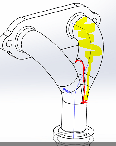
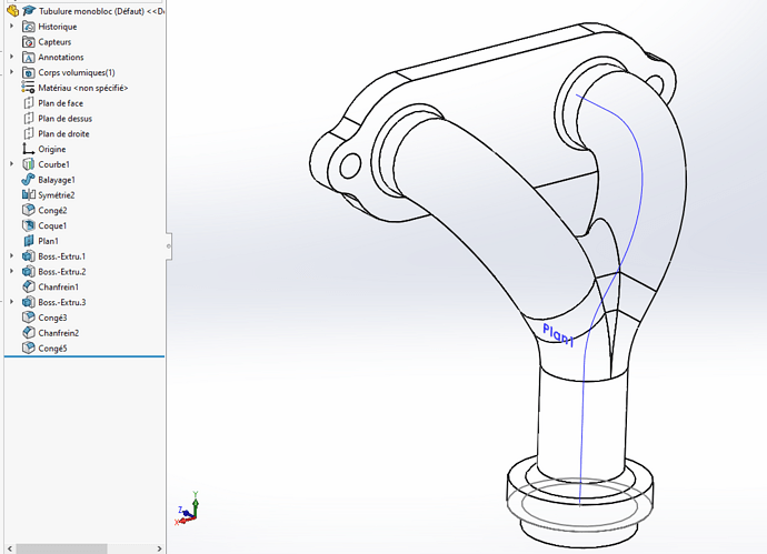
I'm looking for a simple basic technique... To obtain my different elements to make a 2/1 collector, this is my idea, however if I use a non-coplanar composite trajectory, the integrated function of the mechanically welded modeler rejects me and I can admit it.
If someone has an alternative to combine two processes in order to have throughput for the workshop, I am listening.
Thank you for your help and feedback.
Spectrum 2024.
NOK one-piece tubing. SLDPRT (441.1 KB)
Hello
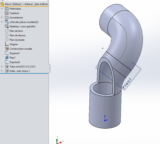
If you want pieces that can be made, you have to design them as they are made: so you start by making a curved tube.
You cut it out here:

You make the tube symmetrical (symmetry of the first or new tube). And then you put the missing pieces between the 2 (solder alone or small rolled part + solder)
The fact of making a projected curve penalizes you. I think you have to go straight through the 3D sketch and create the right radii corresponding to the 3D or 5D elbow.
Then a little removal of matter as Froussel says and a symmetry
of commerce.
Hello
It is also necessary to inquire with the subcontractor who will carry out the bending about the possible radius value.
Or take commercial elbows (thickness and radius according to the manufacturer's data)
Because here you have very little straight part between the 2 spokes, not sure you can do it in bending.
I just reread my answer and I see that I wrote faster than the music ![]() . I meant to use the appropriate radii depending on the trade (3D or 5D).
. I meant to use the appropriate radii depending on the trade (3D or 5D).
On the other hand, bending is feasible but the radii are standard depending on the subcontractor and of course it will be with over-lengths on each side to be cut ![]()
Thank you for the help provided, have a good day everyone.
Spectrum 2024

