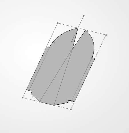
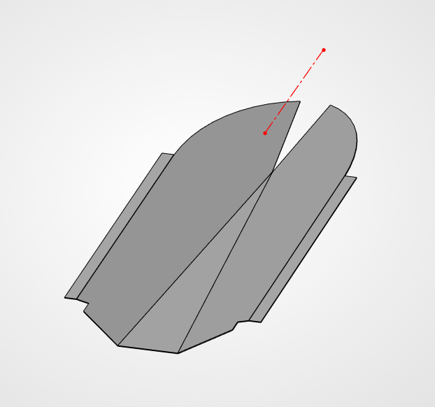
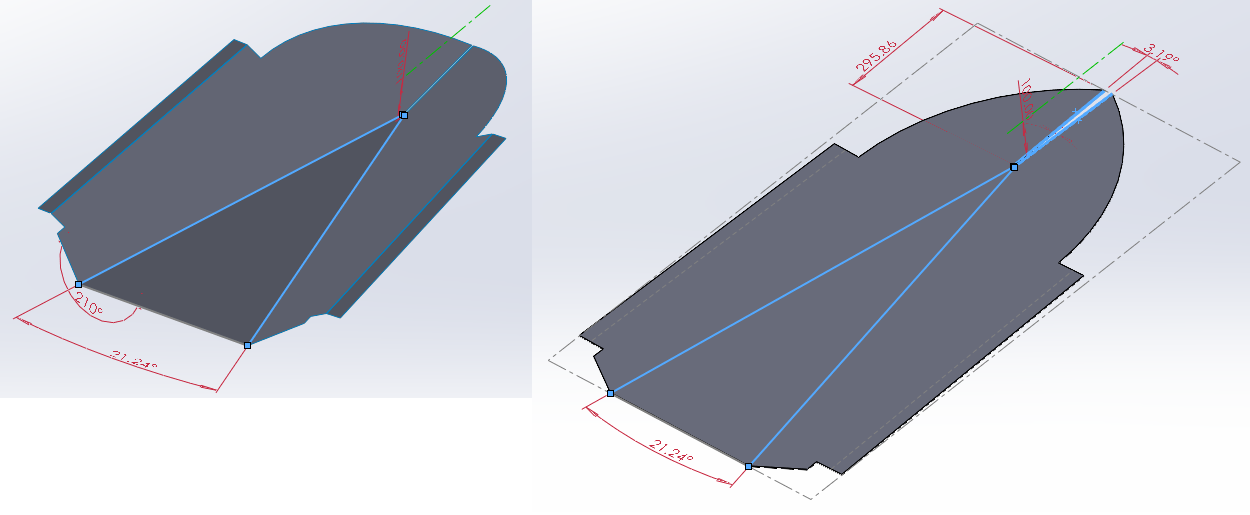
Voila mon problème, j’aimerais courber (déformer?) une tôle avec une coupe centrale en V, de façon à ce que mes deux sommets se rejoignent à une certaine hauteur représentée par mon trait de construction, hors et c’est bien la raison de ma présence ici, je n’y parviens pas.
Je vous joints des captures d’écran de la pièce en question, si jamais je me suis mal exprimé ou qu’il y a un manque d’informations, n’hésitez pas à me le faire savoir.
D’accord avec @froussel pour le principe d’une pièce convertie en tôlerie, mais la conception surfacique a ma préférence…
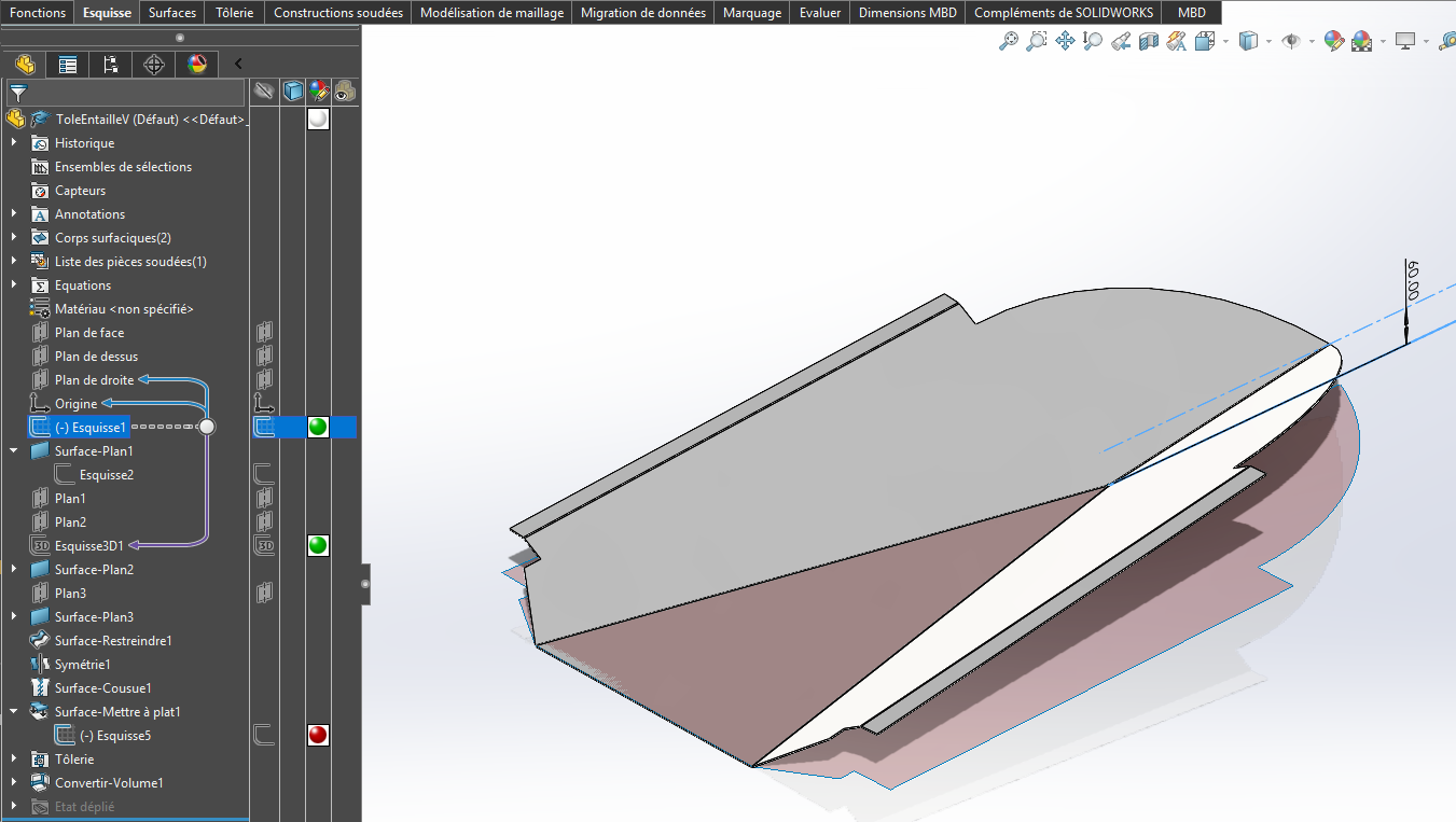
l’Esquisse1 dans le plan de droite permet de définir l’altitude attendue pour la pointe de la pièce.
Génération de la géométrie :
création dans le « Plan de face » de la face plane du triangle de base
création dans le « Plan1 » oblique de la face plane du flanc,
création dans le « Plan3 » de la face plane de la bride latérale.
Dans l’objectif d’une future pièce de tôlerie, la pointe extrême du triangle de base est tronquée (grugeage pour éviter les croisements de plis), et l’arête centrale du flanc oblique est légèrement décalée du plan vertical de symétrie (1mm).
L’« Esquisse3D1 » permet de définir l’arête de l’entaille en V de façon à respecter la cote de hauteur de la pointe.
Pour terminer, symétrie du flanc oblique et de la bride, et couture des cinq corps en un seul (qui peut ensuite être mis à plat).
Le corps surfacique résultant est alors converti en pièce de tôlerie, épaisseur orientée vers le bas, en repérant les quatre plis.
Il suffit de modifier la cote de hauteur dans l’Esquisse1 pour adapter la géométrie de la tôle.
Solidworks 2022, version Education : ToleEntailleV.SLDPRT (1,6 Mo)