Hello,
I would like to model the weld seams on a chassis equipped with IPN beams and angles.
I use solder connectors.
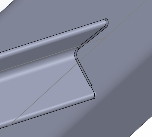
The calculation doesn't work. I have the impression that Solidworks can't work with parts with non-constant fillet or thicknesses on the part profile (IPN beam with different flange thickness from the middle part).
Do you have a method to create the welds?
Thank you in advance.
hello Brice_Delaporte;
Please let us know your version of Solidworks.
For the moment I can't take screenshots of my pc because it's being processed...
But here is already this example=>https://help.solidworks.com/2022/french/SolidWorks/cworks/c_edge_weld_definitions.htm
=>https://help.solidworks.com/2023/french/SolidWorks/sldworks/t_Creating_Weld_Beads.htm
=>https://www.goengineer.com/fr-ca/blog/creating-adding-weld-beads-solidworks
=>https://www.youtube.com/watch?v=zcIrpq-XuQY
and look at this => https://forum.mycad.visiativ.com/t/simulation-avec-des-elements-mecano-soudes-dont-certain-manquant/108508?locale=fr&lang=fr
… Good luck @+.
AR.
Hello,
SW is not efficient and flexible for the creation of weld seams. That's what I can say. So in general I avoid.
However, if it's just to have a visual. You can combine your parts and beams and make chamfers (to be tested).
Of course you won't be able to retrieve for example the lengths of cords for costing for example
1 Like
Hello,
If you have designed your model with the welded construction modules / beams, SW switches the bodies to beam elements in your finite element calculation.
It will therefore be impossible to join your beams (mesh in beam) and your welds (mesh in volume if you are lucky).
Simplest solution: specify that you want to mesh the beams in volume (right-click menu on the beam).
If you want to be realistic, you also have to manage the contacts properly (when your beams touch each other they can't interfere but they are not glued to the other beams: it's the weld fillet that makes the connection). It's the best but it can be long and complicated to model.
If you want to be faster in terms of calculation/modeling, you neglect the welds and you consider that all the bodies in contact are solid.
And if you're a pro, you have fun making a separate model with mixed beam (the current parts) and volume mesh (all the intersections you represent realistically). Nb: leaving a little play between all the beams/parts that are not welded together surely allows you to go faster (avoid having the management of contacts between beams/parts).
2 Likes
I'm on SW Simulation 2020.
In fact I would like to make a stress calculation in the cords, not represent them for a drawing or other.
Is the modeling of a cord necessarily done between two shell elements?
If you want to have constraints in the cords, you will have to represent them realistically.
The constraints at the junctions between beams / surfaces and volume 3D will not give you much fair/representative.
It is likely that your calculation model will be completely different from your 3D design model in the end.
Given the power of current computers and if you don't have a complete building framework to calculate, I advise you to mesh everything in volume (it avoids metaphysical problems in terms of mesh changes).