Yes, agree with you about the throat. But for the moment I still can't create my flat surface around the entire perimeter of the room.
If I interpret your drawing correctly, do you want a curved slope (a kind of downhill bend) between the horizontal plane and the vertical edge of your "headboard"?
Yes, that's right, on my drawing the curves in red represent the radius of curvature of this "curved slope". The size of the spokes are not defined, but around 5mm.
The aim is to have no "sharp" angle in the back of the groove, on the surface of the O-ring bearings and to respect the radii of curvature of the joint.
Thank you for your help and for the time you spend there.
See you soon
Hello
@bernard.bouffil: can you share your piece and maybe the complementary piece.
There may be some geometric peculiarities that restrict or even block the function.
I'm getting a little away from the basic question, but it can play on the feasibility of the piece:
- What material?
- What is the manufacturing method?
1 Like
Hello Stefbeno,
Yes I can share my piece, maybe in a personal message I don't know how it works on this forum, in a STEP format?
The production will be done by casting, ABS or maybe aluminum
See you soon
You can also share it as an attachment to your answer. Format Sldprt would be the most practical, depending on your version of SW.
I have 2 or 3 ideas of possible methods for your curved slope. I'm going to try it out to see the most practical one.
2 Likes
The version I use to draw this piece is the 2019.
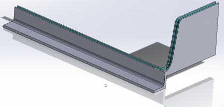
To simplify the understanding of my problem, I have put in dark gray the groove where I will have to position the joint and in red the place where I do not know how to draw a surface continuity between the two faces, as well as the groove.
Thank you
fdc.sldprt
Hello @bernard.bouffil ,
From my point of view, design poses two problems that you have clearly identified in your question:
- how to make a "smooth" connection between the two flat surfaces. To ensure continuity, the connection is a left, complex surface, and I find it difficult to see how to achieve a satisfactory result by means of the volume functions of SW.
- How to generate the groove of the constant section joint. The scanning function seems to be suitable, but on a winding path, the rectangular section undergoes a twist during the sweep, which none of the options can correct.
I have therefore tried to take up the definition of the part (a part) by starting with the generation of its top face with smooth connection, using surface functions. Then, still on the surface, creation of the groove of the joint.
Finally transition to volume and Boolean operation to "machine" the groove.
Model (SW2019) and comments are in the attached zip.
Kind regards.
rainurejoint.zip
1 Like
Hello
Thank you for this work, I'll try to understand what you did, even if I don't know how to work in surface!
I'll try and keep you posted!
Bernard.
Hello
I like the @m.blt method but I have the impression that it does not take into account the bending radius of the joint.
So here is my version: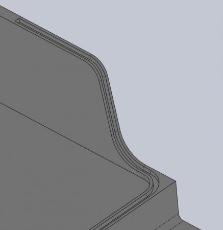
The spokes are probably to be adjusted but it gives you the philosophy of the thing.
Don't forget that there will certainly be remains to be added.
The pocket in the trapezoidal veil seems complicated to me to unmold.
PS: I was surprised by your modeling method (sketches not completely constrained, symmetrical piece not centered, order of functions and parent-child relationship not very appropriate) but maybe it's just a draft piece.
fdc_modifiee.sldprt
1 Like
Hello and thank you again.
To answer your surprise, some additional information:
Yes!! It is more likely that the piece does not follow criteria such as a person with the appropriate skills would. I am trained in electronics and sometimes make parts that are generally quite simple on 3 planes with chamfers here and there, threads, holes..., because their functions are to receive electronic sub-assemblies, heatsinks, or even enclosures. I admit that this part is for me the most complex one I look at, because of this joint.
The reason for my surprising modeling (even if it probably comes from me) may come from the fact that I have cleaned up the part I sent to leave only what is necessary for my request and that this solution is simpler for you. It integrates more functions that do not affect the seal. sketches on the fly.
It is also a (work) part that undergoes a lot of modifications to accommodate sub-assemblies and which serves as a basis for us to define the location of connectors, PCBs, etc. and also its feasibility (by people who would make it ).
For example: even if its design is 90% complete, it allows me to make figures to get an idea of the costs of production.
Then when we start the piece, I don't really have an idea where it will lead us, so I stack the functions one after the other ( I am aware that this sometimes causes me problems, for example sketches that are no longer referenced following the deletion of previous sketches).
In your case, when you draw parts, you have already worked on drafts... and in the end when the part is satisfactory, you redesign it taking into account the order of functions, parent-child relationships...? Or does the skill make it obvious during the modeling of the part?
Thank you again.
I will try to understand your work as well.
Bernard.
I understand this point of view @bernard.bouffil I sometimes make quick sketches or drafts to visualize quickly, or if I don't have a precise idea of the piece. When an idea becomes clearer, it must be immediately redone properly. But in principle with "competence" as you say (I would rather say experience, knowledge and methodology), indeed it flows naturally in the sense that these are things that you anticipate.
1 Like
@bernard.bouffil, indeed it can be explained and as @Sylk rightly says , it is done with experience.
Personally, keeping in mind that there are always parent-child links between functions, I model thinking as much as possible about the subsequent modifications that may be necessary. If you want more details about our habits, I suggest you open another question.
1 Like
Ok thank you.
I'm looking at Stefbeno's solution. Solution that I had imagined at the beginning, where rather than a single "curved slope", we have two distinct radii of curvatures. I had gone from this solution to the one that causes me problems because of the need to enlarge the "headboard" part which supports connectors and this without enlarging the case.
But hey, given my experience and the time of your help, I'm going to enlarge the case and stay on this solution proposed by Stefbeno and I'm also going to look at the surface modeling, but it seems that I have display problems, or is it because I'm not used to this type of modeling.
In any case, thank you all for your help.
1 Like
Hello
Like your piece gave me a hard time and it twisted my pi#e.
So to avoid you, perhaps having to widen your case, you can bring back the "headboard" on the sides: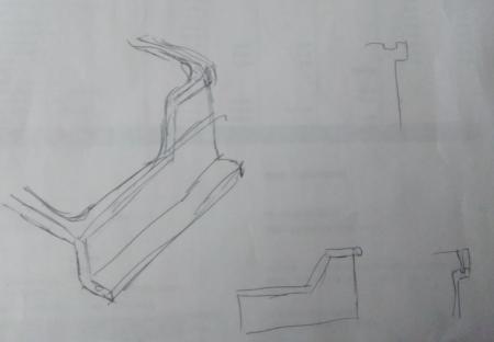
Maybe you can play with the shelves, review with the gasket doc.
First of all, the fact that you put a toroidal ring indicates that you are looking for a certain level of waterproofing. I fear that with this kind of solution it will not be optimal.
You could perhaps go for a solution like this: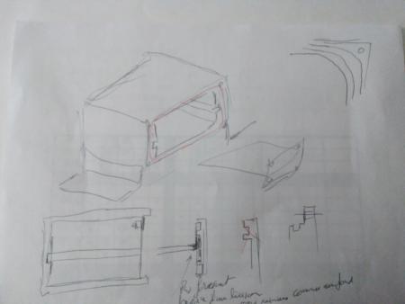
In any case, I think that you will have to plan a serious design review with the manufacturer: depending on the size of the series, the technology chosen, there are plenty of tricks that, for you, will not change anything from a functional point of view, but which can simplify the manufacture and therefore reduce its cost.
img_20220513_135941.jpg
img_20220513_135951.jpg
2 Likes
It is true that without having specifications it is difficult to know the room for manoeuvre as to what is feasible/enviable.
1 Like
Hello Stefbeno and Sylk.
As far as the design review is concerned, it will be more than important! and I am counting on the advice of the companies that will manufacture them, but only when we ourselves have defined as best as possible what we want.
Indeed, I didn't give you all the ins and outs of the whole thing or a specification because I didn't want to feel like I was giving you the baby and making you work, but just to benefit from your help.
But to satisfy curiosity and have a more complete idea (which is normal when thinking about solutions), I attach the whole modeling (step) and also some explanations. The part we have been talking about since the beginning of this post is a "wall box bottom", on which electronic sub-assemblies are mounted and on "The now named: headboard" connectors are mounted. This part is then closed by a "Plastic Hood" to seal the whole. This hood has a second function which is the addition of options, but more than a lot of text, a glance will be more telling.
Due to a lack of information on my part, stefbeno's idea n°2 doesn't work, because on the part you know, the "font of the case" and the headboard can't be dissociated, on the other hand idea n°1 is rather interesting and seems to me to be well to exploit.
- The yellow piece is the one you know.
- The gray piece is the hood.
- The parts in blue are option boxes
- Fuchsia parts are shutters when the option boxes do not exist.
Maybe you will see some differences in modeling, especially on the joint, because I am sending you an earlier version of the step.
Bernard.
assboitier.step
1 Like
@bernard.bouffil: thank you very much for sharing.
My little remarks:
- The hood won't fly off with 10 screws to hold it... I would say that 6 can be enough.
- this junction seems to me a nest to emm##des: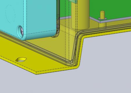
I think that without changing the overall volume (width and height), you can manage to avoid this staircase and have a flat junction: you have to raise the blue boxes a little and maybe go down the floor of the yellow room even if it means slightly recessing the radiator.
- The screw in the top left corner collides with a connector (but you've seen that before).
Hello Stefbeno,
I had in a 1st version, put 6 screws. But taking examples on wall boxes of almost identical sizes , there was a screw about every 10 cm, from which I add 4 screws, I imagined that this is necessary to "crush" the gasket.
As for the junction you show me (the nest of trouble), as you saw in the room you modified, it has changed to avoid this nest of em...
I also changed the position of the joints on the blue cases and the fuchsia covers. They now go inside the holes in the screw hole and aim into the hood mounting holes that have become blind. This avoids the joints and machining that were under each screw.
I'm still working on it.
Bernard.
The idea is that the joint is properly compressed.
Since you don't seem to be in a highly constrained environment (shock, pressure), it is the geometric precision of the parts that will determine your number of screws. It would be better if the parts paired correctly at the base rather than having to force them with the screws.