Creating a Surface Between Two Planes

Hello Stefbeno and Sylk.

As far as the design review is concerned, it will be more than important! and I am counting on the advice of the companies that will manufacture them, but only when we ourselves  have defined as best as possible what we want.

Indeed, I didn't give you all the ins and outs of the whole thing or a specification because I didn't want to feel like I was giving you the baby and making you work, but just to benefit from your help.

But to satisfy curiosity and have a more complete idea (which is normal when thinking about solutions), I attach the whole modeling (step) and also some explanations. The part we have been talking about since the beginning of this post is a "wall box bottom", on which electronic sub-assemblies are mounted and on "The now named: headboard" connectors are mounted. This part is then closed by a "Plastic Hood" to seal the whole. This hood has a second function which is the addition of options, but more than a lot of text, a glance will be more telling. 

Due to a lack of information on my part, stefbeno's idea n°2 doesn't work, because on the part you know, the "font of the case" and the headboard can't be dissociated, on the other hand idea n°1 is rather interesting and seems to me to be well to exploit.  

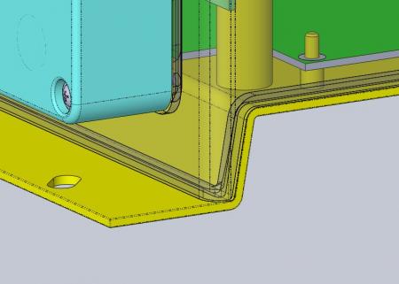
  • The yellow piece is the one you know.
  • The gray piece is the hood.
  • The parts in blue are option boxes
  • Fuchsia parts are shutters when the option boxes do not exist. 

Maybe you will see some differences in modeling, especially on the joint, because I am sending you an earlier version of the step.

Bernard.


assboitier.step
1 Like

@bernard.bouffil: thank you very much for sharing.

My little remarks:
- The hood won't fly off with 10 screws to hold it... I would say that 6 can be enough.
- this junction seems to me a nest to emm##des:

I think that without changing the overall volume (width and height), you can manage to avoid this staircase and have a flat junction: you have to raise the blue boxes a little and maybe go down the floor of the yellow room even if it means slightly recessing the radiator.
- The screw in the top left corner collides with a connector  (but you've seen that before).

Hello Stefbeno,

I had in a 1st version, put 6 screws. But taking examples on wall boxes of almost identical sizes , there was a screw about every 10 cm, from which I add 4 screws, I imagined that this is necessary to "crush" the gasket. 

As for the junction you show me (the nest of trouble), as you saw in the room you modified, it has changed to avoid this nest of em...

I also changed the position of the joints on the blue cases and the fuchsia covers. They now go inside the holes in the screw hole and aim into the hood mounting holes that have become blind. This avoids the joints and machining that were under each screw.   

I'm still working on it.

Bernard. 


The idea is that the joint is properly compressed.
Since you don't seem to be in a highly constrained environment (shock, pressure), it is the geometric precision of the parts that will determine your number of screws. It would be better if the parts paired correctly at the base rather than having to force them with the screws.