Hello everyone,
I want to extrude any two surfaces but I can't find any solution!
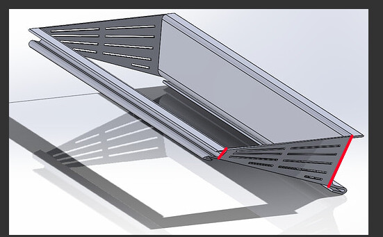
Below is the room to be closed.
Kind regards
Left extension pollen basket with socket and closed side tests. SLDPRT (220.5 KB)
Hello everyone,
I want to extrude any two surfaces but I can't find any solution!
Below is the room to be closed.
Kind regards
Left extension pollen basket with socket and closed side tests. SLDPRT (220.5 KB)
Hello and welcome to this forum,
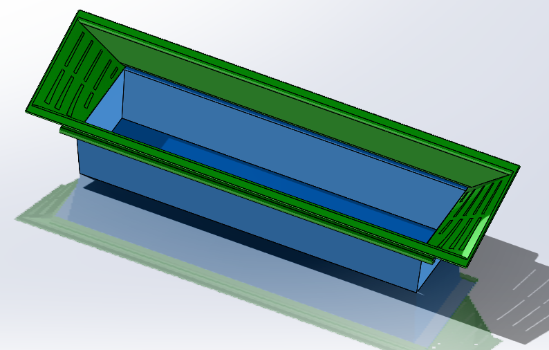
Is the goal to create a wall between the two sides at the open part of the room (in blue below)?
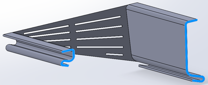
The extrusion you mention could be suitable if the two sides at the ends of the sidewalls were coplanar. As the planes are distinct, the extrusion is not suitable.
On the other hand, a smoothing function is possible, so with left faces...
With which version of Solidworks?
A priori the 23, I can open it with the accessible functions.
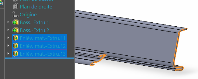
Besides, it's strangely constructed. 3 material removals...
Hello
Attached, a proposal for closure on the basis of a smoothed surface, in SW 2021 version.
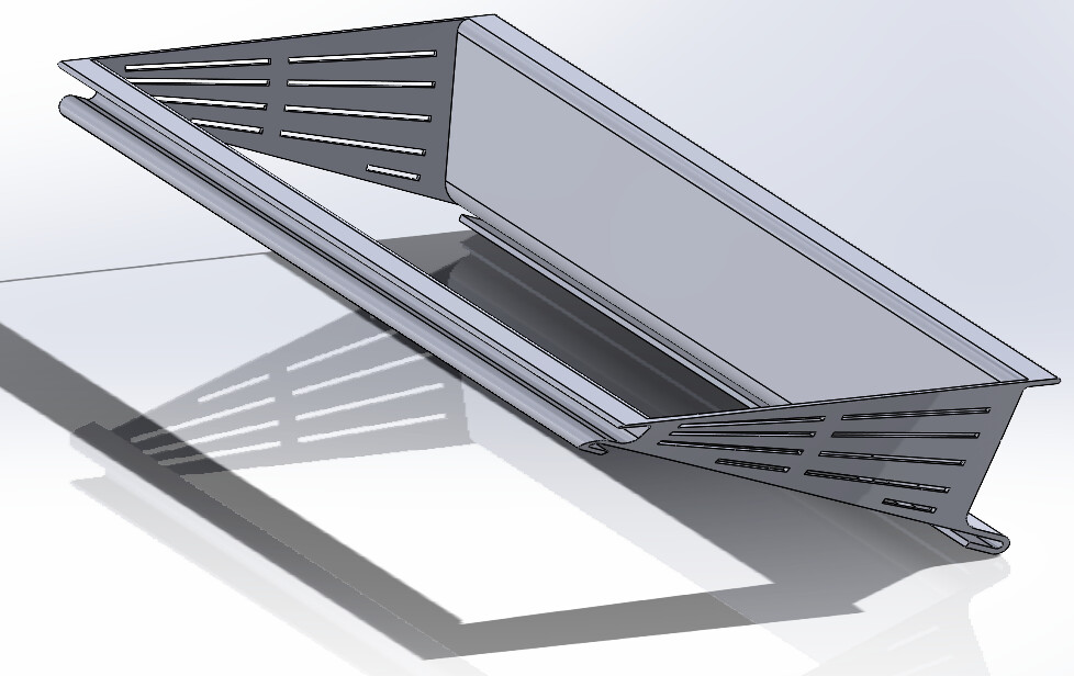
BasketPollen.SLDPRT (462.4 KB)
Hello, thank you for your answers, I have a version of SW 2015
I tried the smoothing function but without result☹️
I'm going to deepen the function hoping to get there, but I'm self-taught on SW so I'm discovering it little by little.
As said before the 2 non-coplanar sides, is it really a choice?
Because if made of sheet metal, it makes the side twist, which necessarily complicates manufacturing.
Does a pollen basket really need this twisted side?
Hello, yes I have no choice, and it's not a sheet metal part but a 3D printing realization
Hello
The modeling steps are described in the attached pdf.
Since you are new to SW, I would like to give you a piece of advice: make sure to totally constrain your sketches, by dimensioning or with geometric relations: tangent, perpendicular...
Nothing is more unpleasant than an unstable sketch that explodes as a result of an unfortunate movement of the mouse. And who stubbornly refuses to return to his previous state with Ctrl-Z...
PanierPollen.pdf (492.6 KB)
Thank you for this help, I will try to apply the method described in the tutorial you sent me.
As for the constraints, it's true that I don't use them because I don't really understand the principle, but I'll follow the advice and watch tutorials about them.
Sketch constraints: the idea is to define, at the level of each sketch, constraints on the dimensions of entities (dimensioning), or relationships between entities: parallel, collinear, coincidental, etc.
With some exceptions, a sketch should be fully constrained before being used to generate a volume or surface function.
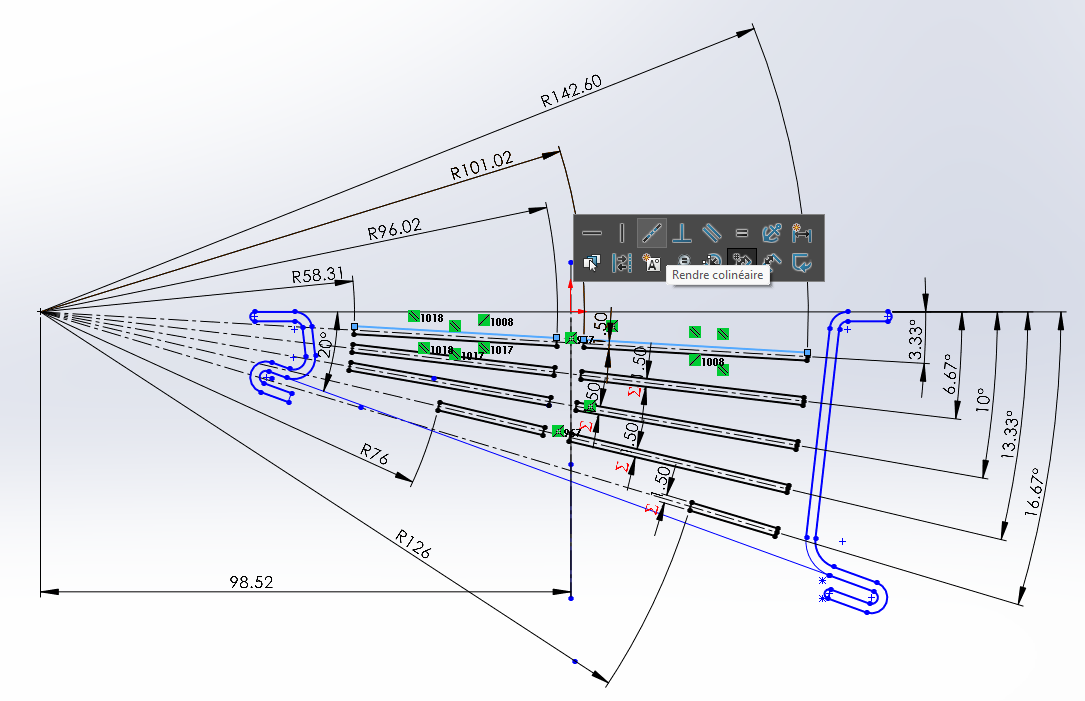
In the image above, the notches in the wall are fully constrained, which Solidworks expresses by a black display. The two selected segments are being processed for a " collinear" sketch relationship.
There is still work to be done to constrain the two sections of the flanks!
For the segments corresponding to the profiles (in blue==> unconstrained) we have the possibility to fix them (anchor). If we add dimension to the fixed parts, it will be controlled (greyed out) dimensioning
Hello, I can't open your file, because I'm on SW2015. Is it possible for you to send it back to me by registering it for a SW 2015 version?
Kind regards
Hello
Sorry, my oldest version of Solidworks was in 2018...
Impossible to save in v2015, and the different export formats do not allow to save the function tree.
The best I can offer you is a video of the wall generation phase, the 2015 version of SW should allow the same construction.
Kind regards
Thank you for your help I will try to follow to the letter, hope it works.
Hello m_blt
I'm relaunching the subject for this piece because after + 6 months of trying various solutions I'm still stuck!
I changed the SolidWorks version of the 2015, I switched to the 2022 version, thinking that I would find the necessary functions more easily, but no, I'm still stuck.
I can't make the extension piece in such a way that it is perfectly adapted to the basket, how to proceed?
Riser and basket assembly 2026.SLDASM (228.6 KB)
Hello
I don't see how there is a bad adaptation of the two plays.
Apart from a few tweaks to adjust the dimensions, the assembly seems coherent.
You should be more precise in describing your expectations: what do you mean by " perfectly adapted to the basket "?
Hello, thank you for your answer, I certainly formulated my request wrongly.
When I superimpose the extension on the basket, we see that the geometry is not identical, the 4 faces of the basket are not // to the faces of the extension.
I put different colors so that it is more visible.
Thank you for your help.
Raised basket assembly. SLDASM (211.3 KB)
Hello
Attached is the modified model to make the bearing faces of the two parts coincide (SW2022)).
I had to slightly modify the area of sketch1 which defines the grooves for the placement of the extension, so as to center it correctly in relation to the basket.
PanierPollenV2.zip (892.8 KB)
Hello
Thank you very much for your help, it seems perfect to me, I can finish my entire project which has been going on for more than 1 year.
I'll post you an overview of the room.
Kind regards
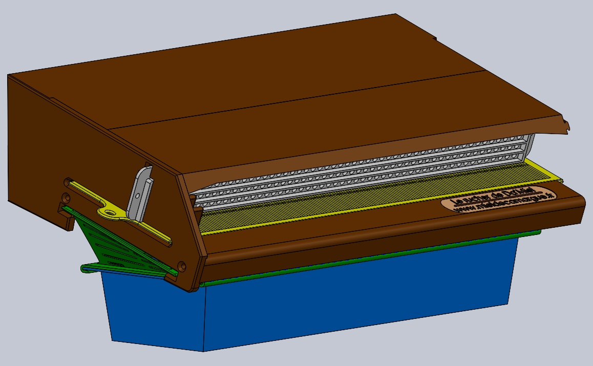
Here's an overview of the part, the right blank is missing, but this will allow you to see what it's for.
Sincerely, and thank you again.
Daniel