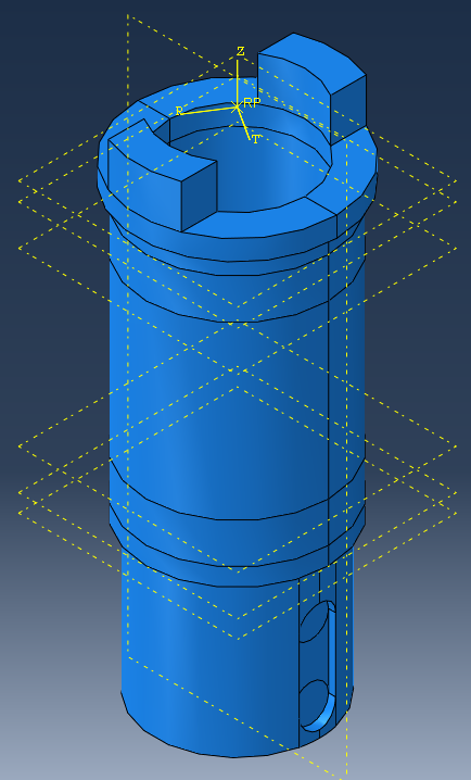
I try to create a symmetry under Abaqus but without success. It's a bit peculiar because it would have to be a plane symmetry but it behaves like an axial symmetry.
Looking at your image, it doesn't look like you're with a haircut. With which software and version number you created the model. Did you create the model entirely as a half part (I don't know anything)
I did make a cut to remove a part, the left (which you can't see anymore) in order to reduce the number of nodes and therefore the calculation time. However, I still need it to be " considered " in the calculation. And that's where it gets tricky... so I tried several methods,
Use a cyclical interaction and it works, almost. The forces are correctly applied but this symmetry " reverses " my right part. So it's not satisfactory
use mirror symmetry. The geometry is good, but at that point it is the forces that are not properly applied
I'm going to reason, as in SW, it could put you on a track for Abaqus.
1°) A cross-sectional view is a view, an image but it doesn't change anything about the integrity of the volume. So two solutions: The bestial method makes you a removal of material corresponding to the part removed but the calculation will not take into account the part removed
But I must admit that I did not fully understand what you want to do 1°) the simulation on one part to lighten the calculation time! 2°) something else you want to do and that I don't understand!
That's it while waiting for your return! Otherwise it's "Tong at the cat"
Thank you for your answer. Indeed I could reduce the problem to a plan solution but this is not the object of the study (since we want to look "exactly" at what is happening in the matter). I'm keeping the idea in mind for a next problem anyway. Thank you for your help!
Under solidworks in the results, using the "design dissection" function you can see the stresses inside the material and even by playing with a cursor see the areas of the most stressed to the least stressed.

 anything)